• Please review our updated Terms and Rules here

Apple IIc power issues

Neo-Rio

Member
Joined
Feb 13, 2016
Messages
40
I'm trying to repair a IIc that seems to be dead on arrival. Turn on switch, nothing happens. No lights, nothing.

So far I've determined that the power supply works. It's getting a solid 18V DC out
It's not powering on anyway.... and from the technical manual I find that the internal power switching board will cut the power to the system if something is wrong with the voltage.

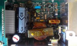
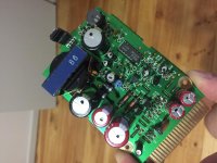
So I've taken apart the power switching box, and looked at the board. It looks OK, but I am suspicious of the voltage regulator which is heatsinked onto the inside of the case in an interesting fashion (with the use of a screw and plate).
I'm looking to try replacing that regulator, but I'm not sure what it is exactly, and what a comparable replacement would be.

It's an NEC C3568

I looked at the SAMS guide, but their diagram of the power switching board looks different to the one I have in my possession.
 
Mine looks completely different.
Perhaps a later revision?

Again, I don't know what voltage the part runs at in order to find something comparable.

IMG_2906.jpg

The regulator part is Q1 - but the SAMS guide has the specs for something that looks like your board - so SAMs is useless.
 
it will cut power if there is anything wrong with the mainboard for FDD or anything else attached, not just the supply
 
it will cut power if there is anything wrong with the mainboard for FDD or anything else attached, not just the supply

If true, where's a good place on the mainboard to use the mulitmeter to check for a good voltage?
 
If true, where's a good place on the mainboard to use the mulitmeter to check for a good voltage?

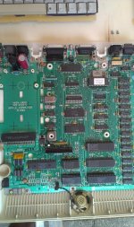
Connect one pin of your multimeter to a metal ground point on the board (D-connector metalcasing for example) and measure the voltage on pin 28 of the system rom (the one with the Apple sticker in the photo) It should give you 5 Volts. You can also check the -5 Volt on the part marked 7905 right most pin if the tab is pointing upwards (mine was defunct and gave -8 Volts)

If 5 Volts is OK then it easier to check further with an oscilloscope for any activity on the CPU and such..

apple_IIc_main_board.jpg
 
Connect one pin of your multimeter to a metal ground point on the board (D-connector metalcasing for example) and measure the voltage on pin 28 of the system rom (the one with the Apple sticker in the photo) It should give you 5 Volts. You can also check the -5 Volt on the part marked 7905 right most pin if the tab is pointing upwards (mine was defunct and gave -8 Volts)

Not getting 5v on either that chip or the 7905.
 
Not getting 5v on either that chip or the 7905.

Next step try and check if the 18V from the external supply reaches the edge connector, if it does check voltages on the uPC494C chip, just be careful not to slip the probe..
This is a switch mode powersupply so a multimeter will only give you average values but the supply pin and Vref pin should be within range.

http://pdf1.alldatasheet.com/datasheet-pdf/view/6776/NEC/UPC494.html

Q1 is the main switcher transistor driving the transformer (Q1 will be driven by the 494) all other supply voltages are from the secondary windings of the transformer.

I'm not sure which pins were the supply and vref pins (I'm no good at reading schematics) , but I tested pin 8 and 12 on the UPC494C chip and found that I could get 18VDC off of them.
 
I'm not sure which pins were the supply and vref pins (I'm no good at reading schematics) , but I tested pin 8 and 12 on the UPC494C chip and found that I could get 18VDC off of them.

18 Vdc at these pins means that it is getting the input voltage, good.
Vref is at pin 14 and should be 5 Volts. If not then the 494 needs to be replaced.

Beyond this you will need some understanding of switch mode powersupplies, feedback, frequencies, opamps and such.
An oscilloscope will be quite handy for detecting activity on the various parts.
 
18 Vdc at these pins means that it is getting the input voltage, good.
Vref is at pin 14 and should be 5 Volts. If not then the 494 needs to be replaced.

...and I'm not getting 5V on pin 14
I'm only getting 1.6v when switched on and 0.6 when off

Might try and find myself a replacement chip and see if that helps?

Is a UA494 or a TL494 16 pin switchmode power controller IC compatible with this NEC chip?
 
Last edited:
...and I'm not getting 5V on pin 14
I'm only getting 1.6v when switched on and 0.6 when off

Might try and find myself a replacement chip and see if that helps?

Is a UA494 or a TL494 16 pin switchmode power controller IC compatible with this NEC chip?

Theoretically yes, they should be compatible but sometimes there are subtle differences, if you can find a NEC chip it is always better.
 
Theoretically yes, they should be compatible but sometimes there are subtle differences, if you can find a NEC chip it is always better.

Removed the old chip, soldered in a socket, found a replacement NEC chip and dropped it in, and hey presto! It boots!

Also passes "System OK" test, however there are still some issues with the machine though. I will open another thread.
 
Back
Top