clh333
Veteran Member
The Atari 850 module was designed to interface the 8-bit Ataris to serial and parallel peripherals. The computer communicates with the 850 by means of Atari's SIO bus, essentially serial but with a proprietary connector, and offers four serial and one parallel port to peripherals. An internal microprocessor and ROM routines handle the conversions.
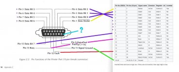
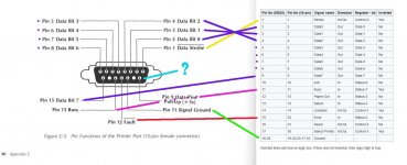
However, the parallel port is neither IBM-standard 25-pin nor Centronics-standard 36-pin, but is a D-sub female 15-pin. I am attempting to construct a cable which will connect with the Centronics interface. I have a question about one of the lines coming out of the Atari 850: I'm not sure what to do with it.
In the attached diagram I have taken the port configuration from Atari documentation and drawn lines of communication to standard connectors, as given in Wikipedia, and can account for strobe, data, ground, busy and error / fault, but the Atari also is outputting +5VDC on pin 9. Atari describes this as "data pin pull-up".
I have no idea if I need this and am hoping someone can provide some insight. Thanks for your replies.
-CH-


