• Please review our updated Terms and Rules here

Bringing Up a Vector Graphic MZ

MarsMan2020

Experienced Member
Joined
Dec 19, 2013
Messages
188
Location
Hawthorne, CA
I recently acquired a Vector Graphic MZ from a friend. The exterior is somewhat scraped up, but the inside is in excellent condition. It has 2 5.25" full height floppies, and 4 cards:
-A ZCB Z80 SBC/CPU Card
-A 64KB Dynamic RAM Card
-A Micropolis Floppy Disk Controller
-A Flashwriter II terminal card.

What would be the best approach to getting this machine online? My first thought was to take all the cards out, disconnect the power leads from the floppy disks, and start checking voltages.

Assuming all the DC voltages are what they should be, put it back together and start it up.....

Then the question is how to talk to it, since I don't have a Vector Graphic terminal to match up with it?
 
I have the same system except I also have the Bitstreamer II serial board. I verified power in the same manner you described. After that, I brought up the computer running just the ZCB and a serial terminal, and then proceeded to bring up the additional components from there.

How many DB25 connectors are on the rear of your MZ? One is most likely wired to the Flashwriter board for the Mindless Terminal. Is there a second DB25 as well? If so, does it have a ribbon cable connection to the ZCB?

Let me know and we can take it further from there.

Mike
 
I have 2 DB25s - one that goes directly to a DIP style socket on the ZCB, and one that goes to the daughter card for the Flashwriter II.

I took a series of pictures of the chassis and boards - http://imgur.com/a/zb8k8#0

Where/how can I get a key to actually power it up? Should I just take the whole thing to a locksmith? I don't really want to mess with the sweet turnkey switch.
 
For testing, we can probably get the ZCB up and running as the only board in the system if you want. A different monitor ROM can be installed so we can run the monitor through the ZCB serial port.

Your Flashwriter is configured for a Mindless Terminal. The FW can be modified for composite video out if you don't want to buy a MT. You can then have a FW based console by adding a parallel Keytronics keyboard, or by using the serial port on the ZCB for keyboard input, but the FW for display. I've done this both ways.

I haven't studied the PS/2 to parallel keyboard adapter you mentioned in your other post to know for sure whether it can generate the same keycodes generated by the Keytronix keyboard used with the VG.

Mike
 
I'm still working on this. I did some checks that the large capacitors in the power supply trend towards high resistances over time when measured with a voltmeter, and that the appropriate terminals are grounded, per the "pre-power checks" section of an MZ Mainframe manual I found online. So that's a good sign.

I also found that the 5A fuse + the cap of the holder are missing from the back of the unit, so I'm getting a replacement. And I have an appointment at a locksmith tomorrow morning to get a key made to be able to actually power the system on.
 
So I got a key made, and a replacement fuse holder cap (Littelfuse 342, in case anyone is interested), took out all the cards and unplugged the floppies, and turned the system (well, the power supply really) on.

Good news: No sparks or magic smoke, and the fan turned on.
Bad news: +8V rail = 11V, +16V rail = 23V, -16V rail = 23V

So, what do I do now? "Just tear out that ancient power supply and replace it with some switching power supplies" has occurred to me, but I had hoped to avoid such drastic rework on a nice unmolested vintage system....
 
Those are normal readings. This kind of power supply, with no load, would return values higher than with load. Check for ripple using an oscilloscope or just proceed to the next step...plug in a RAM card and check the voltage coming from a voltage regulator on the card. Are you getting, for example, + 5v on the right most pin of a 7805 on a test card inserted into your backplane?
B
 
Last edited:
Those are normal readings. This kind of power supply, with no load, would return values higher than with load. Check for ripple using an oscilloscope or just proceed to the next step...plug in a RAM card and check the voltage coming from a voltage regulator on the card. Are you getting, for example, + 5v on the right most pin of a 7805 on a test card inserted into your backplane?
B

The two "mini floppy power supply" boards that are permanently wired into the power supply system read +5 and +12 V on the dot on their +5/+12V outputs from their regulators.
 
Exciting! So the next step I suppose is to install at least the ZCB + RAM board and try and boot it with some kind of ROM.... I have to admit to being kind of new to Z80 & CP/M-land, I just built an N8VEM Zeta SBC so I would have a "modern" Z80 system to work with, but otherwise this is all kind of new to me.

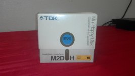
I have the ZCB, which appears to have some kind of ROM mounted in it, and I also acquired off eBay a set of "master" and "system" discs for Micropolis floppy systems, and a box of 10 still-in-the-shrinkwrap (!!) DS/DD 5.25" floppies with 16 sector holes....

I imagine the ROM that is in there is setup to use the Flashwriter card, so I probably need to get a modern EPROM or EEPROM equivalent to the ROM, and program it with a ZCB-only ROM image to get going?

Or is there some kind of floppy jump-to-address setup that would allow me to load boot code off one of the Micropolis floppies?

I am going to hold off on any mods to the Flashwriter board for now because I may have located (fingers crossed) an actual Mindless Terminal to use with this machine.
 
We can test with just the ZCB board if you want (it has some on-board memory at FC00-FFFF), or you can install the 64K RAM board as well. We need to figure out exactly what version of the ZCB you have (more to it than looking at the "REV" number shown on the silkscreen, unfortunately) and how your ZCB is jumpered so we can create an EPROM that will properly operate your system through a serial port.

We can move quickly from there to putting in more boards and then attempting to boot from your floppy drives. If needed, I have a mechanism for creating new boot floppies on your MZ from a large collection of floppy disk images for the MZ. See http://altairclone.com/downloads/vector_graphic/mike-vector-graphic/Disk Imaging Utilities/

Here's a link to a document that will help determine your "real" ZCB revision: http://altairclone.com/downloads/vector_graphic/vector-graphic.info/Manuals/Vector-ZCB-1-B-misc.pdf

IGNORE the REV number shown on your board while you read through the identifying characteristics. If you can, shoot me a close-up picture of your jumper area "F." It looks like some mods have been done there. In fact, send me close-ups of any jumper area that has traces cut and/or jumpers installed.

Mike
 
Mike - I uploaded a set of close up photos to http://imgur.com/a/2gLbv

There is a modification in Area F, U35 appears to have been replaced, and it looks like there are modifications to U4/U26/U33 that may match what is handwritten on Page 5 of the PDF you linked. A1-2 has a trace, there is 1 PROM installed at U20, and the Y1 crystal is 8 Mhz.....
 
Looks like your board is still rev 2 but the race condition mod for the 64K RAM card has been done. A bit of a hybrid!

This means a 2716 is still expected in U20, however, I have also used a 2732 with the desired program in the upper 2K of the 2732 and that also works. The faster 2732's are easier to find.

Do you have access to EPROMs and a programmer? If so, I can send you a hex file to program into a 2716 or 2732 and you can then bring up the VG monitor on your ZCB using the serial port. If not, I can burn an EPROM for you.

We can do the monitor two ways: A) modify the default serial port in the monitor ROM (port 2/3) to match your ZCB port (4/5), or B) change jumper area E to put the ZCB serial port at 0/1 and 2/3. Option 1 will work with CP/M and MDOS disks that use the monitor for I/O (e.g., the VG branded CP/M). However, most of the Lifeboat CP/M versions and my routines for reading and writing disk images go straight to the serial port at address 2/3. For this reason, I'd consider option B or adding a Bitstreamer II card to your system.

Finally, if you're thinking you'll have the Mindless Terminal soon, you may want to bring up your system with that and use the ROM that is already in the ZCB and no serial port at all.

Mike
 
Could I use a 28C16 EEPROM instead of the 2176 EPROM? I don't have a programmer, I've been thinking of getting one of the inexpensive TOP ones off Amazon just to get started.

The Mindless Terminal might be a little ways out so I'd rather get the ZCB tested while I get that going.. If I wanted to do Option B, would I be cutting a trace and adding a jumper in Area E? I'd love to have a Bitstreamer II to add to my set of boards, but not at the price of the single board that is on eBay right now....

Andrew
 
A 28C16 should work. Do you have a system in which you can program the 28C16?

If you choose option B, then yes, in area E you'll have to cut the 1-4 trace on the back of the board and add a 1-3 jumper. That should make the port appear at I/O address 2/3 (and 0/1).

HOWEVER, this configuration causes a conflict with the keyboard status and data register of the FlashWriter which is also at I/O address 0/1. You'll have to restore the jumper configuration when you're ready to use the system with the Mindless Terminal along with the original ROM and the FlashWriter.

Based on the FlashWriter conflict, maybe an option C is in order. Start with option A (modify the monitor to use I/O address 4/5 for the console) so that the serial port jumpers don't have to be changed on the ZCB. Then, I could modify my disk imaging routines to use I/O address 4/5 instead of 2/3 so that you could generate bootable CP/M and MDOS disks in addition to the disks you purchased (or if the ones you purchased don't work). This way, the only limitation would be that some of the Lifeboat CP/M versions that do console I/O directly through I/O address 2/3 won't work. Again, the VG versions of CP/M and MDOS will work as they call the monitor entry points for console I/O. By the way, we can easily modify Lifeboat CP/M through their "User Area" mechanism to create a version that uses port 2/3 for console I/O.

OK, you convinced me. Let's do option C instead. Let me know if you have a way to program the 28C16. If not, I can burn and loan you a 2732 for a while.

Mike
 
Last edited:
I'll have a few 28C16s and a programmer arrive sometime in the next week or so. I was planning to get the programmer anyway for folks to use at the makerspace I am a member of.

I appreciate all the help - I'm looking forward to getting this thing up and running!
 
Hopefully I can create and test the PROM this weekend. Then I'll post the binary and Intel hex formats for you.

The disks you bought are probably the generic Micropolis FDS disks (MDOS and BASIC) that Micropolis shipped with their external drive packages for S100 machines. The disks are most likely not boot-ready for your MZ unless the seller told you they were configured that way. The Master disk is before system-specific configuration (mainly console I/O) and the System disk is after system-specific configuration. I have the manual that came with those drive packages that describes how to configure the disks for a specific machine. Let me know if you need a link to that manual.

We also have a couple of different ways to get you other bootable disks for your MZ (several variations of CP/M and MDOS), so if your drives are functional, we can get you up and running one way or another!
 
I was able to create a modified monitor ROM and run the monitor, CP/M and MDOS using the ZCB serial port for console I/O. Let me know when you get your programmer and then I'll post the monitor .hex file along with a few other useful files. I'll do a little more testing in the meantime.

Mike
 
Back
Top