rorypoole
Veteran Member
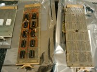
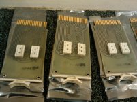
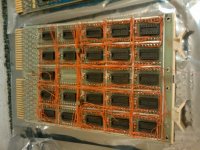
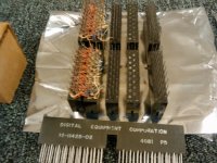
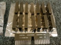
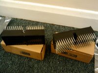
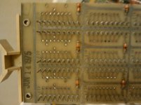
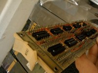
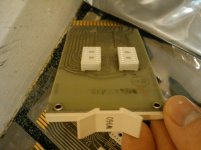
some great pics of a pdp8, useful info on core memory boards in the pics, I need to find info on the 51 and 52 red transformers some time
http://www.computerhistory.org/revolution/minicomputers/11/331
http://www.computerhistory.org/revolution/minicomputers/11/331


6sGWg~~60_57.jpg")