• Please review our updated Terms and Rules here

Cf-XTreme - testing phase

Pikkey

Member
Joined
Jun 3, 2009
Messages
33
Location
Treviso, Italy, Italy
cfxtreme.jpg

Hello guys, only to show what's going on here.
Just assembled.
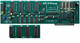
This is a prototype of ISA board with IDE controller, CF slot (still missing) and memory expansion (2+2 Mb ram)
This is a project we started to think about almost two years ago. Finally we did it.
Next days we will test it, hoping all is right.

(Forgive me for my bad english)
 
I am definitely interested in this card. You have done a very good job.
I do have a few questions though.

* I can see that your EMS page frame options are C000, D000 or E000, but what memory address options do you provide for the boot ROM? Due to the design of my XT clone I am hoping to fit the boot ROM into F000-F3FF (since the BIOS on this XT only takes up the upper half of the Fxxx range and the external ROM checks up to F400). Would this be possible by modifying/rewiring the card?
* Is it possible to use a CF card through the IDE connector (using an IDE-CF adapter)? I am hoping to mount my CF somewhere I can access it outside the case.
* Does your XT-IDE adapter provide the "Chuck mod" to allow faster data transfers than standard XT-IDE cards?
* Will you be providing these in kit form (at a discount)? I can solder everything but surface mount, and if I can use a IDE-CF adapter I won't need the CF slot.
 
Very nice indeed.... I am wondering though why such a big card? Looks almost full length... Not that I mind it - I like the look and heft of the old full length multi-purpose cards with the RAM daughter boards but I would think if you were going full length you would cram more functions in there (e.g xt-fdc as well).
 
Well it is an XT-IDE and EMS card in one, and it also uses DIP ICs instead of surface mount like other cards. There is some space lost between the memory chips and the CF slot also takes up a lot of room. It could be shrunk, but not by much (unless you swap to small surface mount chips).
...And I agree adding floppy controller support would make it even better... ;)
 
The EMS section at least appears to be a copy of my work, currently this is not licensed.
 
We desired to make a board that seem to be "vintage". There were option to change pcb colour and to simplify the electric design, but here we are "old" inside ;)
 
* Yes, you can move the boot address cutting a track and soldering a couple of jumpers. A simple hack.
* Yes , even if we didn't complete the tests yet
* maybe :) With a 4 mhz bus of common XT's, it seem hard to improve the transfer rate. We'll see.
* we have a very short number of ready pcb and your question is too in advance . As way of think, we don't have anything against the idea of people who build it by themself :)
 
The space between the memory chips is used by the chips on the sandwitch board. It makes the look "skinny" when the sandwitch board is mounted
 
Last edited:
Thanks for your replies, with the limited number of ISA slots in this XT your card would be ideal for my needs. Especially since it provides up to 4MB EMS (vs the 2MB max of the lo-tech card).

What are the (normal) ROM address options for the CF adapter? I didn't see the answer to that in your replies.
 
What are the (normal) ROM address options for the CF adapter? I didn't see the answer to that in your replies.

the rom is allocated in C8000h but on the board there is a jumper to move it to the D8000h in case other "special" rom is present in your XT.
Is possible to move the rom in other different locations playing with some (simple) hacks
 
Last edited:
Back
Top