GearTechWolf
Experienced Member
I think I've had this board (and most of its peripherals- sensors, head-motor, heads) since I was in the single-digits of age, back when I thought smacking circuit-boards with a hammer was great fun.
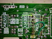
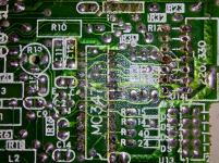
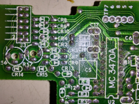
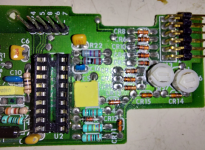
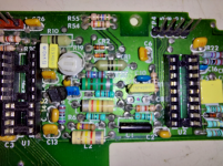
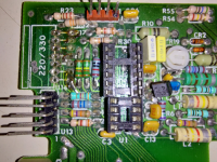
Now I'm much wiser and I'm trying to repair this board (plus the two controller-boards from a ST4038, but those are much more damaged) and aside from the missing chips (which I've replaced with sockets, including a couple trace-repairs) I'm now at a stand-still.
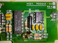
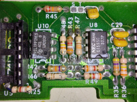
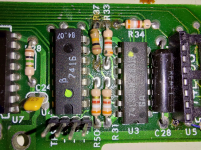
I don't know what the missing transistor at Q1 is supposed to be, the value of the rectangular capacitor at C8, the value of R27, nor what used to go at the space marked 220/330. (although I think it may have been a block of config switches?)
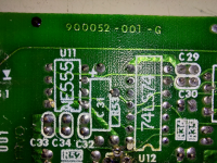
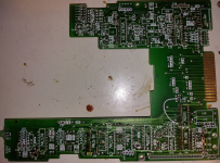
Board is marked ASSY. 900053-00(6?) REV D (silkscreen with faded hand-written 6 and D over white blocks) on top, and 0984 001 (date-stamp?) FRVO 900052-001-G (etched copper) on the bottom. There are no further markings.
Head stepper/servo is a SANKYO SEIKI MFG. CO., LTD NO. (BLANK) JAPAN TYPE MSHF200B71 VOLT DC[12]V motor with five wires on a six-wire connector.
Head assembly is stamped 24 JUL 1984 and has a sticker that says AMI 39456.
Head optical limit-sensor assembly is stamped 8423 (date?) MEXICO on one side and HOA6035-1 on the other.
The two optical disk-detection assemblies are unmarked, or at least have no surviving marks on the remaining plastic mounts.
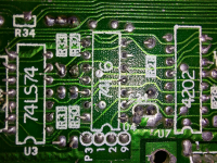
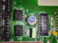
The UCN4202ABU chip (spindle-driver?) is cracked at the corner by its 16th pin and may or may not be still functional.
The board is missing the MC3470A, MC3471, 74LS08, and two 7438 chips due to their destruction.
There is a 74LS04N in a location designated for a 74LS74 according to the silkscreen, it came this way from the factory.
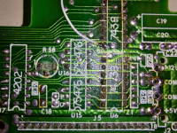
It also has two UDN5711 MBU where the silkscreen calls for a pair of 75476's, also apparently as-factory.
Any help identifying this unit and/or pics of an intact board would be much appreciated!
Here's the pics: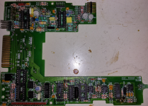
Underside pics in second post.
Now I'm much wiser and I'm trying to repair this board (plus the two controller-boards from a ST4038, but those are much more damaged) and aside from the missing chips (which I've replaced with sockets, including a couple trace-repairs) I'm now at a stand-still.
I don't know what the missing transistor at Q1 is supposed to be, the value of the rectangular capacitor at C8, the value of R27, nor what used to go at the space marked 220/330. (although I think it may have been a block of config switches?)
Board is marked ASSY. 900053-00(6?) REV D (silkscreen with faded hand-written 6 and D over white blocks) on top, and 0984 001 (date-stamp?) FRVO 900052-001-G (etched copper) on the bottom. There are no further markings.
Head stepper/servo is a SANKYO SEIKI MFG. CO., LTD NO. (BLANK) JAPAN TYPE MSHF200B71 VOLT DC[12]V motor with five wires on a six-wire connector.
Head assembly is stamped 24 JUL 1984 and has a sticker that says AMI 39456.
Head optical limit-sensor assembly is stamped 8423 (date?) MEXICO on one side and HOA6035-1 on the other.
The two optical disk-detection assemblies are unmarked, or at least have no surviving marks on the remaining plastic mounts.
The UCN4202ABU chip (spindle-driver?) is cracked at the corner by its 16th pin and may or may not be still functional.
The board is missing the MC3470A, MC3471, 74LS08, and two 7438 chips due to their destruction.
There is a 74LS04N in a location designated for a 74LS74 according to the silkscreen, it came this way from the factory.
It also has two UDN5711 MBU where the silkscreen calls for a pair of 75476's, also apparently as-factory.
Any help identifying this unit and/or pics of an intact board would be much appreciated!
Here's the pics:


Underside pics in second post.

