• Please review our updated Terms and Rules here

Debugging an RX01/RX02 on an RX8E in a PDP-8/e

I did some more debugging today. Yesterday the processor died. If it executed an Operate instruction the PC got loaded with a strange address. Replacing the M8310 Major Register Control board fixed it.

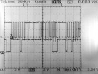
RX_Data.jpg
In this image you can see the RX DATA and the D3 CLK BUFF L signals when the RX8E and the RX02 are talking.
The Status word says that the drive is not ready, so I have some RX02 debugging to do.
 
Lou,

When I started this PDP-8/e project the M8650 had just one failed SN7474 IC, so that was an easy fix. Both 8k core stacks had different problems, so they were replaced with a 32k RAM board from Vincent. In the last two months the M8300, M8310, and M8330 all failed and were replaced with spares. After I get the RX8E/RX01, TD8E/TU56, and MI8E working I will make two extension ribbon cables so I can put the processor and core boards on an extender and repair them. If I get all of that working I might get brave and start looking for an RK8E. Details on this project are here: http://www.ricomputermuseum.org/Home/equipment/dec-pdp-8e/pdp-8e-restoration-log

I have a long term project to connect an Actel SmartFusion FPGA to the Omnibus so it can emulate peripherals that I don't have. The idea is to put time sensitive logic like address decoding, skip, data break, and interrupt in the FPGA and do all of the non-time sensitive emulation with Linux device drivers and Linux applications running on the ARM in the FPGA. There is enough RAM in the SmartFusion so I could copy a disk/tape image from flash memory to RAM, emulate disk/tape from the RAM image, and copy the RAM image back to flash when the processor halts. Having the flash images of the disk/tape in Simh format would be convenient. The SmartFusion has analog I/O so I could emulate an A/D converter. Another enthusiast suggested making a Web peripheral where you would write a URL to the device, the SmartFusion would fetch the file from a Web server, and then the 8e application could read the file from the Web peripheral. Kind of like NAS for the 8e. I did a proof of concept project like this for the PDP-8/L. Info is here: http://www.ricomputermuseum.org/Home/equipment/pdp-8-l/making-a-posibus-periperal-emulator
 
Sounds like a great project. You are fortunate to have boards to pull and swap. I have gate chased problems in my central processor (and repaired them) three times over the years. (No swap boards here, but boatloads of TTL, scope, logic analyzer, prints, the three volume service manual set.) I hope the swap boards get repaired - these boards are not cheap or easy to come by.

Lou
 
I've found that bringing an old machine up after a long time without power does end up with a few IC failures. I've had to replace several in the one I'm working on at present. Mine have generally worked to begin with but died after a few operating hours. I guess that moisture has found it's way in over the years and then the heat when powered up leads to an early failure.

As you say though - it's important to fix the boards where possible, they are now quite scarce on the secondhand market. I have only a small stock of TTL and it can be a longish job looking for a spare then finding that you worked it out wrong. I have an extended memory controller playing up just now which can set any field from power-up but not change it after that. Some memory stacks which are a bit flaky too - I find them near-impossible to work on with marginal fails and difficult access.
 
The team at the Rhode Island Computer Museum revived a PDP-9, PDP-8/S, 8/L, 8/I, and now the 8/e. The common procedure is to replace the AC capacitors in the ferroresonant power supplies first because they always fail. Then connect just the power supply to AC through a Variac and very slowly increase the voltage while measuring the voltage on the caps, looking for bulging caps, and measuring the temperature of the caps. We also look for electrolytic caps on the boards, and reform them. Once the power supply works OK we can power up the system at full voltage.

The 8/S system required cleaning, front panel bulbs, and power supply caps, but not much else.

The 8/L required repairs to 28 Flip-Chips and had the symptoms that bobaboba described. It would run for a while and then die. We replaced lots of SN7474 ICs and a few other TTL parts.

The 8/I was stored in a poor environment for a very long time and required repairs to 51 Flip-Chips. The ICs that failed were mostly SN7474 and SN7440. The most difficult issue to find was a broken Wire-Wrap wire on the backplane.

Warren made a Flip-Chip tester that was a huge help with testing and repairing the 8/I, 8/L, and the spare Flip-Chips.

The PDP-9 is transistor only like the 8/S. It is microcoded and has lots of delay lines that must be adjusted by Wire-Wrap jumpers on the backplane to control timing. It is much more complicated than a PDP-8, but does have some built-in diagnostic capability. Using two 'scopes and a logic analyzer at the same time was the only way to debug it. It has been a significant challenge to get running and keep running, and spare boards are rare and expensive.

The PDP-8/e is actually a lot easier to debug than the 8/I or 8/L. With everything on one board we can just put the suspect board on an extender and start debugging. I have an HP logic comparator that I will start using on this system. You put a known good IC in the Logic Comparator, clip the probe over the suspect IC, and run the machine. Any difference in the behavior between the known good IC and the one on the board will show up in the LEDs. I need to make ribbon cables for the cross-over connectors so I can debug the CPU and core boards. As long as the current set of CPU boards stays working I will work on the diskette and tape subsystems. If the CPU dies again I will fix all of the CPU boards so I have spares again.
 
Sounds like a great project. You are fortunate to have boards to pull and swap. I have gate chased problems in my central processor (and repaired them) three times over the years. (No swap boards here, but boatloads of TTL, scope, logic analyzer, prints, the three volume service manual set.) I hope the swap boards get repaired - these boards are not cheap or easy to come by.

Lou

Personally I find repairing boards stimulating and very satisfying and would add lots of coffee to the "tools" needed :) so far the only ones that have defeated my are actual failed core stacks.
I do have quite a few ;)
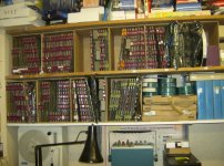
HPIM2064.jpg

Dave
 
Personally I find repairing boards stimulating and very satisfying and would add lots of coffee to the "tools" needed :) so far the only ones that have defeated my are actual failed core stacks.
I do have quite a few ;)Dave

I agree that it is satisfying to track down a broken IC and fix a board. The RICM has a pile of repaired and tested Flip-Chips that looks like yours. We put tags on them indicating the failure and what was replaced to fix it. Warren Stearns made a Flip-Chip tester that connects to the parallel port on a PC and uses SPI expander chips to control and read the signals. It was really helpful getting the 8/I and 8/L running.

Warren's board tester doesn't do negative logic, so on a few occasions we jumpered a few Flip-Chips together to test Flip-Chips from the PDP-9. That would also work for a Classic PDP-8, TC01, TC02, TC58, TC59, etc. We have a big stack of PDP-9 Flip-Chips that need to be repaired.

I have swapped email with several people who have repaired core stacks from early DEC equipment. Usually the wires in the core stack were broken and soldered during manufacturing. The solder joints come apart after 40 years and need to be resoldered. The later core stacks used in the PDP-11s are probably too dense to repair.
 
I did some more RX8E debugging yesterday. I debugged the Transfer Register test that I wrote. That exercised and validated more logic.

I tried the RX01 again. Pressing the CLEAR key did not reset the RX01. I replaced the digital board with one from a desktop RX01 and now it almost always resets in the CLEAR key. It is nice to see the heads move and the head load solenoid activate. It looks like the processor is not always activating the INIT signal on the Omnibus when you press the CLEAR key or execute a CAF instruction. Power cycling the whole system fixes that issue. I will debug that later.

Reading the RX01 Status and Error Registers exercised the remaining RX8E logic, so I think that the RX8E is ready to go. I see the Drive Ready and INIT Done bits in the Status Register, and a error code of 0170 Data AM not found in allotted time, or 0200 CRC error on reading the sector from the disk.

I started looking at the signals on the analog board. The disk Index pulse for DK0 is every 170 ms, for DK1 it varies a lot. The drive door latch is not working well so the hub is slipping.

I will write a sector buffer test this week.

Next Saturday I will replace the right diskette drive with a NOS spare. I will also look at the signal from the head and trace it back through the digital board. I should check the diskettes on a PDP-11 because they might have been damaged by all of the debugging and experimenting.
 
The intermittent with the CLEAR key turned out to be in socket E7 for one of the microcode ROMs on the M7726 logic board in the RX01. Wiggling the ROM fixed it for now. I need to take all of the ROMs out and treat the sockets with DeoxIt for a permanent fix. After fixing the microcode problem the DIRXA controller and the controller-interface diags passed and printed a "C" after every pass. I tried the complete diskette diagnostics and saw the same 0170 Data AM not found in allotted time, or 0200 CRC error on reading the sector errors.

Earlier this week Warren and I came up with a plan to look at the differential signals from the diskette head, and work through the Op-Amps to the One-Shots. I really couldn't see any more than a few millivolts from the diskette head, so I verified that the head select logic was all OK. I swapped the diskette in case it was damaged by earlier experiments, and noticed that there was a radial wear line on the diskette where the head touched. I poked a flashlight inside the diskette drive and was not really surprised to see that the diskette spindle was not turning.

Last week, I had disassembled the right drive to remove a big red piece of plastic and a cardboard puzzle piece. At the same time I cleaned the head, the index and track 0 sensors, and put the drive belt back on the pulleys. It is not unusual to have the belt stick to the pulleys and fall off if the drive hasn't been used for a very long time. I stopped debugging then, and forgot to do the same procedure this week for the left drive. I put the belt for the left drive back on the pulleys and now I could see the head stepping out the tracks when the diag was running.

It still failed, but with mostly with a 0200 CRC error on reading the sector errors. I tried several different diskettes and got different results. I ran a cleaning diskette in the drives, and didn't see any improvement. I dug through the warehouse looking for NOS single-density 8" diskettes. I found lots of double-density and some hard-sectored diskettes and just a few single-density. One of the NOS diskettes works perfectly and the left drive passes all diagnostics. It prints a "D" at the end of every pass.

I need to find more good single-density 8" diskettes or get one of the S-100 systems that will format diskettes working. Next week I will try David Gesswein's restrx01 program to see if I can copy an image of a diagnostics diskette to a real diskette. If that works, the diskette should boot to OS/8.
 
Don't forget to check the little felt dot on the underside of the head load solenoid arm. Sometimes it's gone, sometimes it's really smashed down.

Any person intending to do much with an RX01 should set up a PC with an 8" floppy drive. Then with PUTR and IMGDSK you can format RX01 media, make complete images of your disks, and even work with the files of RT-11 or OS/8 formatted disks.

I've written about it here before, but I take dime-a-dozen double sided floppies, punch the index holes through the jacket in the right place, and then have RX01 flippy disks (one RX01 on each side). Format them on the PC and you're good to go.

If you're really serious about 8" floppies, you'll also get an analog alignment disk. All of its usefulness has been explained here before also.

Lou
 
Lou,

I think that the trick is finding a PC that has a floppy controller that is versatile enough to be used with a variety of diskettes. I will go through my collection of PCs and see what they have for controller ICs.
 
I used DeoxIt to clean and treat the microcode sockets in the RX01. Hopefully the RX01 intermittent is gone for good.

We booted OS/8 through the serial port using Kyle Owen's serial server, and used the OS/8 RXREAD program to test some 8" floppies. Out of the stack of diskettes from a variety of vendors we found three that worked OK. I need to get a PC setup with an 8" floppy so I can format and image 8" diskettes.

I used David Gesswein's dump/restore programs to copy an image of an OS/8 diskette to a real RX01 diskette. After trying three different RX8E bootloaders, the one in the OS/8 manual booted OS/8 from the diskette that we just made. I even ran BASIC from the diskette, so that probably means that the processor is working OK.

SYS VOLUME-- 1
SYS:=RX8E
OS/8 SYSTEM VERSION 3Q

BUILD .SV 33 HELP .SV 8 BASIC .UF 4
ABSLDR.SV 5 PAL8 .SV 19 BCOMP .SV 17
BITMAP.SV 5 PIP .SV 11 BLOAD .SV 8
BOOT .SV 5 PT8E .BN 1 BRTS .SV 15
CCL .SV 18 RESORC.SV 10 EABRTS.BN 24
CREF .SV 13 RXCOPY.SV 6 RESEQ .BA 6
DIRECT.SV 7 SABR .SV 24 ECHO .SV 2
EDIT .SV 10 TECO .SV 22 RKLFMT.SV 9
EPIC .SV 14 BASIC .AF 4 SET .SV 14
FBOOT .SV 2 BASIC .FF 4 BATCH .SV 10
FOTP .SV 8 BASIC .SF 4 FUTIL .SV 26
HELP .HL 55 BASIC .SV 9 IDS .SV 5

36 FILES IN 437 BLOCKS - 1 FREE BLOCKS

The right diskette drive is not working well, so we still need to fix that.
 
Most excellent. Congratulations!

You will find very soon that you'll want to configure your MI8E for the RX01 bootstrap. Fat fingering it in gets old fast.

For someone else here I placed my MI8E on a flatbed scanner and took a picture. All one needs to do is follow the picture and put all the diodes and jumpers in the right places. I worked it all out by hand myself when I did it, but there is no sense in anyone going through the same pain.

Lou
 
Last edited:
I used DeoxIt to clean and treat the microcode sockets in the RX01.

Which one, and how? I've seen general mention of DeoxIt in various contexts, but their product line seems to have a plethora of variants.

I'd like to learn more about your/others experiences & uses, please :->. Thanks! [Maybe this topic deserves a new thread?]

-----
paul
 
Which one, and how? I've seen general mention of DeoxIt in various contexts, but their product line seems to have a plethora of variants.

I use both DeoxIT® D-Series (D5S-6) and DeoxIT® Gold G-Series (G5S-6). I use the D-Series for cleaning and lubricating tin contacts, and the G-Series for gold contacts.
 
You will find very soon that you'll want to configure your MI8E for the RX01 bootstrap. Fat fingering it in gets old fast.

I have been RIM loading the RX01 bootstrap, but getting the MI8E working is next on my list. The MI8E prints don't include the RX01 bootstrap so I would be interested in having a copy of your picture.

I found many different RX01-RX02 bootstraps, but only the one in the OS/8 manual worked.
 
Mike,

Send me a PM with a proper e-mail address so I can mail you the photo (and anyone else interested.) It's too big for the photo album here on the forums, and the high resolution is important. Perhaps you can post it for everyone somehow with your project blog.

Lou
 
Back
Top