• Please review our updated Terms and Rules here

Debugging an TU56 on a TD8E in a PDP-8/e

m_thompson

Veteran Member
Joined
Jul 8, 2014
Messages
1,985
Location
Rhode Island, USA
Now that the diskette on my 8/e is mostly working I am looking at the TU56 DECtape. The H-716-B power supply has no voltage on the -15VDC output. That shouldn't be difficult to fix.

The Command & Data ribbon cable looks like it got caught under one of the cabinet casters when the cabinet was moved. Just a few of the wires are damaged, so I should be able to repair it.

The only set of Engineering Drawings for the TD8E that I found are somewhat poor quality. In many cases the IC numbers and signal names are unreadable. Does anyone have a clean set of TD8E prints or a better scan?
I have re-drawn the schematics some time ago: http://svn.so-much-stuff.com/svn/trunk/Eagle/projects/DEC/Mxxx/M868/
If you need me to convert them to a PDF or the like, let me know. The board drawing hasn't been sync'ed up with any particular DEC revision, so I'd ignore that. Also, the ECO that CJL is always talking about has probably not been folded in. I'm still looking for a board with a proper implementation of the ECO.

I may also have some replacement data cable boards that I had made up a couple of years ago.

Vince
 
Vince,

Could you email me a PDF of your schematic? I may try marking up the PDF of the DEC schematic so it is readable.

I have seen a lot of different revisions of the TD8E. I have no idea if the DEC schematic is even close to the controller that I have.

The controller to transport cable that I have only has some damaged wires in the middle of the ribbon cable. The boards on the end are OK. It should be repairable.
 
Could you email me a PDF of your schematic? I may try marking up the PDF of the DEC schematic so it is readable.

I have seen a lot of different revisions of the TD8E. I have no idea if the DEC schematic is even close to the controller that I have.
I have sent you a copy of the schematic, and I also checked one in, so it should be available along with the Eagle stuff now.
My schematic should match the DEC drawing (let me know if it doesn't). It also matches my Rev. H board in the few places
I have checked.

Vince
 
We removed the ribbon cable that connects the TU56 DECtape to the TD8E controller. It looks like it got caught under a cabinet wheel and damaged some of the wires. The H-716-b power supply for the TU56 should make +5VDC and -15VDC, but the -15VDC is broken. Both of these should get fixed during the week.
 
Transistor Q7 is missing from the H-716B power supply, so that explains why the -15VDC doesn't work. The schematics that I have found so far are in poor condition, so I can't see the part number for Q7.

Does anyone have a clean scan of an H-716B power supply schematic, or have a power supply and can supply the Q7 part number?


Never mind...
There is a schematic decal with part numbers on the inside of the power supply. Q7 is a 2N3569. Bought a bunch on eBay.
 
Last edited:
I replaced transistor Q7 with a 2N3956 that I bought on eBay. Both +5VDC and -15VDC now work. Tomorrow I can see if the TU56 transport will work with the local controls on the front of the drives.

I fixed the two broken wires in the bobbon cable that connects the TU56 DECtape to the TD8E controller. There are some spots on the ribbon cable where the insulation was worn down to the bare wires. I will tape it for now, and look for a better solution later.
 
The TU56 power supply works fine with the replacement transistor installed. There is a problem with the Forward motor controller for the left drive. The Forward and Reverse both work OK on the right drive. I can swap board between the left and right drives to localize the problem.

Two indicator bulbs are out on the drives. I ordered replacements and will install them next week.

I toggled in a little program to read the switch registers and write to the Control Register. I can make the right drive go Forward and Backward. I can see Mark Track and Data Track data from the right drive when the tape is moving.

There is a drive select problem with the right drive. It gets selected OK and responds to commands, but it does not echo the right voltage back to the controller to indicate that it has been selected.
 
This is an encouraging thread ;o). I've just got an 8/e up and running after a smattering of TTL failures and running OS/8 using Kyle Owen's pcserver at the moment. Console is a bit slow because I only have an M865 for it - anyone have a schematic for this board (not the 8650) so I can look at hacking it a little?

I have an as-yet-untried TD8E/TU56 combination to hook up to it so it's nice to hear someone making progress. The switches on my TU56 are stiff and sticky and I don't think they're making good contact, and the bulbs seem to have died so it looks as though some careful dismantling is called for - anyone done this? Any tips would be appreciated as I'm a bit worried about breaking something.
 
This is an encouraging thread ;o). I've just got an 8/e up and running after a smattering of TTL failures and running OS/8 using Kyle Owen's pcserver at the moment. Console is a bit slow because I only have an M865 for it - anyone have a schematic for this board (not the 8650) so I can look at hacking it a little?

The M865 and M8650 are probably close enough so that you can determine the jumper changes and the crystal change to make it work at higher speeds.

The switches on my TU56 are stiff and sticky and I don't think they're making good contact, and the bulbs seem to have died so it looks as though some careful dismantling is called for - anyone done this? Any tips would be appreciated as I'm a bit worried about breaking something.

You should be able to squirt some contact cleaner in the switches and get them to work. Mine had to be turned on/off quite a few times before they were reliable.

I ordered CM2182 bulbs from Digikey. I will disassemble the indicators, cut out the existing bulbs, and solder new ones. Hopefully I will do this on Saturday.

You can read the details on the restoration here: http://www.ricomputermuseum.org/Home/equipment/dec-pdp-8e/pdp-8e-restoration-log
 
The M865 and M8650 are probably close enough so that you can determine the jumper changes and the crystal change to make it work at higher speeds.
I'm not so sure.

The M865 is described as being 110 baud and current loop only. I'm using it with a 20mA interface. I guess I can change the xtal to get 150 baud and powers of 2 (?) but I don't think it has the level shifters for RS232 which I'd need to add. Not looked properly yet though so who knows ...
 
Sorry for hijacking this thread. I'll start another one if it bothers anyone, just say, but it seems relevant as I'm just starting to connect up/debug a pdp-8/e, TU56, TD8E system.

First off, I'm planning to run the TU56 on its own. I have a dual variable psu handy so I think I only need to connect mains, +5V and -15V right?

Second (when I get there) where would the TU56 normally get its +5V and -15V from? Can it come from the 8/e? (where?). I can always rig one up if necessary as it seems to be relatively low current.
 
I got mine in a swap a few years ago but no H716b. It's taken me a while to get the rest of the bits together so I've just started looking at it.

I can easily put together a +5/-15V supply of course and meantime I'll run it from a bench psu.

Would it be practical or advisable to run it from the 8/e supplies? They've plenty of capacity for a single TU56.
 
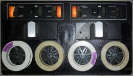
TU56_DECtape.jpg

I also replaced the bulbs inside of the WRITE and SELECT indicators on the drives. DEC field service would replace the complete indicator assembly, but they are no longer available. Doing some surgery and replacing the bulb inside the indicator with a CM2182 was not difficult, and looks just fine.

Replacing the defective G848 Motor Control Flip-Chip in the left DECtape fixed the problem where the tape was always rewinding.

I wrote a little program that reads the Mark Track from the DECtape, finds and puts the block number in the MQ register, and reverses the tape direction when it sees to the end of the tape. I have two of the TD8E Omnibus TD8E boards that interface the TU56 DECtape drive. With TD8E #2 the tape just rocks back and forth when the program is run, and the block number is either 0707 to 7070. With TD8E #1 the left drive works correctly and shows increasing and decreasing block numbers as it scans the tape. This means that the Timing, Mark, and Data tracks for the left drive are all working, and lots of the TD8E is working. With TD8E #1 the right drive rocks back and forth and the block number changes from 0707 to 7070. I will ignore TD8E #2 for now because TD8E #1 will be easier to diagnose and repair.

I looked at the Timing and Mark Track data from the two DECtape drives.The Timing and Mark Track signals from the left drive show a pair of 8us pulses at a 13ms interval when the drive is stopped, and pulses at a 18us interval when running. The rising edge of the Timing Track signal is centered on the Mark Track signal. This is how it should be.

The right drive shows constant 20us signals on the Timing Track, and 4us signals on the Mark Track when the drive is stopped or moving. Something is really wrong with the Mark Track signal. I swapped all of the related Flip-Chips from the left drive to the right drive, but didn't see any changes to the right drive's Mark Track signal behavior. The left drive still worked correctly with the swapped Flip-Chips.

Any ideas what I should try next?
 
After talking to some experts, I did some more debugging on the TU56 tape drive. It looks like the right tape head is bad. On Dectapes there are redundant tracks for everything. One part of the tape head for Mark Track data has an open connection where it should be about 35 Ohms. I doubt that the tape head is repairable, and it is quite a project to replace.

I did some more work on the TD8E tape controller using the left tape drive. The controller & drive will read a tape, but will not write a tape. There is a problem reading the Command Register in the tape controller. These will be the debug projects for next Saturday.
 
Since the right DECtape drive has a defective tape head we went back to working on the TD8E DECtape controller. This board has a repair tag on it from 1980 that says that it can't write, and the TD8E diagnostic said that it could not write and then read the Command Register.

We used Kyle Owen's os8diskserver to emulate an RK05 disk drive and booted OS/8. We were a little surprised to find that we could list directories and read files from the left DECtape drive. That means that most of the TD8E controller and the left TU56 drive are now working. Some of the DECtapes that we tried were dated 34 years ago and still read without errors. That is pretty amazing.

DEC diagnostics will do a good job of making sure that everything is working as expected, but they are sometimes not very useful for debugging a specific hardware problem. I wrote a little program to read the front panel switches, write them to the TD8E Command Register, then read the Command Register and put the result in the MQ register. The contents of the MQ register can be seen on the front panel.

All of the Command Register bits worked except for the Write bit. No surprise there. We found that the Flip-Flop that holds the Read/Write bit did not Set when the Write bit was written. I wasted quite a bit of time looking for the source of the CLEAR signal to the Write Flip-Flop. I had disconnected the TD8E DECtape drive, so it would not interfere with debugging. After a long while I found that just about any error in the TD8E or DECtape will clear the Write Flip-Flop. Connecting the TU56 DECtape drive made all of the errors go away, but the Flip-Flop still would not Set.

We have found lots of failed SN7474 Flip-Flop ICs in other DEC projects, so we replaced it. Unfortunately that didn't change anything. Prior debugging projects also showed that if one of the input pins on the ICs that are driven by the Flip-Flop is shorted to ground the Flip-Flop will not change it's state. DEC actually uses this Flip-Flop behavior on some boards and drives the Flip-Flop output pins. We went looking for all of the ICs driven by the Flip-Flop. The only copy of the TD8E schematic that have is difficult to read, so that was a challenge. For the ICs that were common 74 series TTL we just cut the input pin connected to the Flip-Flip and looked at the Flip-Flop output again. We ran out of time before we found the failed IC.

We looked at the Write Flip-Flop behavior on the second TD8E, and it did Set and could be read back. At least we know it should behave as expected.

During the week we will trace the connections from the Write Flip-Flop on the TD8E and annotate the difficult to read schematic. Next time we will have a better idea of what ICs are driven by the Flip-Flop and could cause the failure.
 
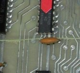
I think that I found the problem with the Read/Write Flip-Flop on the TD8E. DEC installed an 0.01 uF capacitor between +5V and the CC R/W (1) H signal from the Flip-Flop. The other TD8E has the cap between +5V and Ground, and another TD8E that I looked at also has the cap between +5V and Ground. One leg of the cap is in the right via, the other leg should go in the via to the left. This error will take just a minute to fix. Maybe this TD8E never worked?

Does_not_work.jpg
 
Back
Top