• Please review our updated Terms and Rules here

Dual purpose M8560 Serial board

Mike_Z

Veteran Member
Joined
Dec 1, 2013
Messages
1,713
Location
Near Milwaukee Wisconsin
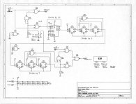
I use a M8650 serial board in my real PDP8e. The terminals that I use is either a CIT-101 at 9600 baud or an ASR33 at 110 baud. My issue is that in order to change from the CIT-101 to the ASR33 I also have to pull the M8560 board and replace it with one that works at 110 or 9600 baud. For the past few weeks, I've been thinking about how to add something to the M8650 board so that I can just use a switch to change the baud rate. The problem is that 110 baud is not a factor of the 9600 family of frequencies. After looking at the M8650 schematic, it appears that the 9600 board has a 1.9661 Mc clock. This is divided down to 153.6 Kc and 19.2 Kc for the board to use 9600 baud. Trying to figure how to use these for 110 Baud
19.2 Kc/110 = 174.55 can not get 1/2 divide
38.4 Kc/110 = 349.09 this is pretty close to 349
I figured that if I could insert a divider of 349 in the division line I could get the 1760 and 220 cycles needed to generate 110 baud. Problem is that 349 is a prime number, making it difficult to build a divider. Then I thought that how about using a divider of 350 and place it at a higher frequency spot in the division line. If I use the 1.2288 Mc (E22 pin 7) as the input of my 350 count divider and connect the output of my 350 divider to pin 14 of E18 I could get really close to 110 baud

1.2288 Mc/350 (new 350 divider) = 3.511 Kc / 16 (existing E18) = 219.43 cps

This is really close to the needed 220 cps for 110 baud. So, I figured using a 7490, divide by 10, then a JK flip flop divide by 5, followed by a JK flip flop divide by 5. Then with a toggle switched control circuit the would connect the original counters into the circuit for 9600 baud or switch out the original counter for the new 350 counter circuit.
350Divider.jpg
Do you think this should work? Thanks MIke
 
I think one of those divide-by-5 needs to be a divid-by-7? Other than that it sounds promising.

The M8655 does something similar with a different base frequency and divide-by-13 and divide-by-15, IIRC.

Vince
 
Vince, thanks for the reply. Sometimes I can make mistakes faster then the PDP8. I have two serial boards both M8560's one set for 110 and the other for 9600. I was unaware of the M8655 board. I'll have to look into that one.
My construction skills center around perf board and wire wrap. I figure the first step is to temp the wiring up and see if it works. Then I may need some help on assembling some kind of sister board. I have some experience using KiCAD, but only for making schematics, nothing more. Maybe something small like this can be made on a PCB. Anyway, let me see if I can get the logic to work first, then ..... Thanks Mike
 
Today I drew up this schematic with Ki CAD and ordered some parts. I plan on initially building the circuit on perf board with wire wrap (something I'm very familiar with) and can easily repair my errors. Mike
 

Attachments

  • M8568Divide350.jpg
    M8568Divide350.jpg
    267.2 KB · Views: 20
Today I drew up this schematic with Ki CAD and ordered some parts.
Cool! There's some redundancy in your design. The R1 side of the switch isn't doing much, since you can just let the divider run even when it isn't in use. I also think the component count could be reduced by using more LS90 instead of a lot of LS73. All you really need is the divide by 5 side of a decade counter (assuming it works that way?), and then an AND circuit to reset the divide by 7 whenever the three low bits are all set. Or possibly to glitch an extra count in that case, then ignore the high bit, but that would want a binary counter instead of a decade counter.

OTOH, building it in the way that seems most obvious may make debug easier and faster.

Vince
 
Hmm. U3A seems to be hooked up so that the alleged divide-by-5 divides by 6? It''s hitting reset if count reaches 6, which means states 0...5 are permitted.

Vince
 
Oooppppsss... I think you are correct about the divide by 5. It is easy to forget about the zero first count. It's an easy fix. Didn't think about using a 7490 as a divide by 5, or a binary counter for a divide by 7. I may look into that.
I understand regarding the input switching. So, I could just connect the divide by 10, 7490, directly to the input and eliminate the U1 NANDS and the first switch. When I was working ( seems like a million years ago), I could always count on a friendly jab in the ribs about mistakes, etal. Thanks for the help. Mike
 
Vince, following up on your suggestion regarding a binary counter, I found a 74ls163 which can be cascaded. I drew up this diagram for a 349 counter. Basically it loads an initial count of 1699, then counts up to 2048, reloads 1699 and counts up again. 2048 - 1699 = 349. I don;'t have any 74ls163 chips so I had to order some. But this may work better than the ripple counters. Thanks, MikeDivideBy349.jpg
 
Hey Mike, if you are going to go to this much effort you might consider making a clock such that the final baud rate is 115200. I am pretty sure you could make the logic on the M8650 clock at that speed.
 
Doug, not sure I completely understand. Are you implying, make a separate clock on the new board, or change the clock on the M8560 board? and added counters for all the common baud rates? Mike
 
This might be getting too in the weeds, but would be nifty to have a tiny microcontroller generating the correct baud clock by sniffing the receiver line and using a simple algorithm to determine the incoming baud rate, then set the clock accordingly. Then, you could simply swap cables (or have a clever switch arrangement to swap between current loop and RS-232), press a few keys to give the auto-baud algorithm some data, and voilà—no removing and reinstalling boards or setting DIP switches!
 
Where I come from it's called "the Pucker Brush". I don't know, but this may be beyond my abilities. Sure would be neat thou. Mike
AND.... my old boss would call it project creep.
 
I know your original intent was to allow for switch selecting between 110 and 9600 baud and that seems like a reasonable goal. But since you are already looking at adding 3 additional IC's it might end up being simpler to use a baud rate generator IC with the correct oscillator and then select the one you want with a dip switch. And as you point out, this is a definite feature creep.
 
Vince, following up on your suggestion regarding a binary counter, I found a 74ls163 which can be cascaded. I drew up this diagram for a 349 counter.
Seems OK. There may be details about whether the 2048/0 state counts or not that I don't know about, but an off-by-1 wouldn't be hard to adjust for.

I'm not sure if the pulse generator is needed at U?A or whether the clock output will be cleared by the load. Without looking hard at the data sheet, I don't know if you need to de-assert count enable during the load, either.

Maybe someone with more expertise can tell us if we still need the 1K pull-up resistors these days? Or can we just tie LSTTL inputs to +5V directly?

Vince
 
Vince, I ordered a bunch of the 74ls163's. They should arrive next week. I plan on bread boarding them to see if I interpreted the data sheet correctly or not. That's part of the fun. Let you know, Thanks, Mike
 
Maybe someone with more expertise can tell us if we still need the 1K pull-up resistors these days? Or can we just tie LSTTL inputs to +5V directly?
Okay to tie LSTTL directly to +5V. Standard TTL specs for input current at maximum input voltage are specified at only 5.5 volts, but LSTTL specifies the i_I at 7 volts.

Back in the day we would still tie LSTTL inputs to pullups so automatic test programs could test the boards. Testing was done one IC at a time, so board test development could be just a collection of tests for each IC rather than a custom test based on the board's function. If we tied too many inputs to the same pullup or tied them to +5V, then the test engineers would have to customize the test programs for those ICs.
 
Vince, following up on your suggestion regarding a binary counter, I found a 74ls163 which can be cascaded. I drew up this diagram for a 349 counter. Basically it loads an initial count of 1699, then counts up to 2048, reloads 1699 and counts up again. 2048 - 1699 = 349. I don;'t have any 74ls163 chips so I had to order some. But this may work better than the ripple counters. Thanks, Mike
I think this is a good general approach for a divide-by-N circuit. The '163 was one of my favorite digital ICs because it's completely synchronous and so versatile.

You may want to make a few minor adjustments...
* The 12-bit counter counts up to decimal 4095 (0xfff) where the final terminal count signal is asserted. You'll probably want to load 0xea3 rather than 0x6a3. This way it'll load decimal 3747 and count up to decimal 4095 and load 3747 again and repeat.
* The '163 features a synchronous load. It will only load the Q outputs from the D inputs when pin 9 is low and there's a rising edge on clock (pin 2). The present schematic has two NAND gates that create a narrow sliver pulse to the LOAD signal. That won't load the counter (because the load, PE/, is a synchronous input). To fix this, simply invert the TC (pin 15) from the counter on the right and feed the inverted final TC back to all three Load inputs (PE/) which are on pins 9. This will load decimal 3747 on the next input clock rising edge after a count of decimal 4095.
* Just tie the P inputs (pins 7) high (pullup or +5V, whichever you prefer). No need to do any special gating to control the P count enable. The PE/ Load on pin 9 takes priority over the count enable signals (pins 7 and 10).
* The TC output, pin 15, is internally a combinatorial logic function of the Q outputs and the T input, so it can have glitches depending on differences in high-to-low and low-to-high delays of the Q outputs and delays in the T to TC chain from previous stages. You might get lucky and have no glitches or you might not. You could clean up the TC output with a flop or gate with clock, but even better... the easiest thing to do since this circuit divides by a single value is to use the highest counter bit that toggles as your output. Assuming the new load value is 0xea3, this would be Q0 (pin 14) of the '163 counter on the right. That Q0 will toggle at the input divided by 349 and have no glitches (because it's an output of a counter flipflop). Q1, Q2 and Q3 are loaded with ones and stay at one in this count range, so Q0 is the one you want to use.

Also, note that the beauty of your synchronous design is that any glitches on the inverted TC output won't bother the PE/ input because everything operates on rising clock edges.
 
Your description reminds me that the DG Nova Basic IO Control has an upgrade daughterboard that is sometimes patched in to accomplish a similar result ... but uses the '161. It starts with a 12.672 MHz OSC and then provides jumper-based selections from 9600 down to 75 baud. I've attached a copy of the schematic for your delectation :-}.
 

Attachments

  • 107-000572-01 IPL TTY Oscillator Board - Schematic.pdf
    55.5 KB · Views: 10
Back
Top