bitfixer
Veteran Member
General electronics question:
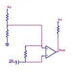
As part of my exhibit for VCF east, I need a little circuit to take an audio signal (sine or square wave, AC coupled, between approx -1.5v to 1.5v or so) and convert it to a digital signal (0v to 5v) such that each period of the wav that dips below 0v creates an output voltage of 0, and where the sine wav is positive, it creates 5v.
I have a simple op-amp circuit that sort of works. Although it is noisy and the part that should be 0v output is more like 0.8 v or so.
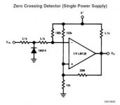
I'm thinking that the easiest way would be to add a voltage to the AC coupled audio through a voltage divider, then use a comparator to make the output voltage 0 to 5v. But my attempts have so far been of limited success. Anyone have a circuit example that could help? Thanks!


