- VCF South West - June 14 - 16, Davidson-Gundy Alumni Center at University of Texas at Dallas
- VCF West - Aug 2 - 3, Computer History Museum, Mountain View, CA
- VCF Midwest - Sept 7 - 8 2024, Schaumburg, IL
- VCF SoCal - Mid February 2025, Location TBD, Southern CA
- VCF East - April 2025, Infoage Museum, Wall NJ
-
Please review our updated Terms and Rules here
You are using an out of date browser. It may not display this or other websites correctly.
You should upgrade or use an alternative browser.
You should upgrade or use an alternative browser.
Ensoniq EPS classic repair. 68k cpu
- Thread starter foofles
- Start date
Look to see if the byte (or the previous two bytes) before the text string matches the count of the bytes in the string. If so, then look for that address.
Sadly, no luck with that.

I did find other text with references to it though. I'm thinking whatever code is loaded from the OS floppy disk must tell it to display the error text I'm seeing. Getting the code out of the floppy image I have doesn't sound like a fun time since ensoniq used a non standard floppy format.
I guess I'll just play around a bit more with the hardware once I can get it out of storage.
Edit - I actually found a total commander plugin that will let me look at the contents of these ensoniq floppy images. The file has no references to the address of the error text in the rom, *but* this file has a header at the top that presumably wouldn't be loaded into ram. I dunno if I want to keep going down this rabbit hole more right now, haha. :D I guess I'd have to dig through the disassembly of the rom to see exactly what it's doing with the data from the floppy, and that does not sound like something I want to be doing
Last edited:
Actually, after thinking about it, it wouldn't even matter where the code from the floppy was loaded into memory, would it? It should still have the address of the text I'm seeing if it does indeed have the code that uses that text. I might play with ghidra a bit more. Very well could be something I'm doing wrong, but it automatically discovered what was referencing some of the other strings!
..... Hello.
I've resurrected an old thread.
I have a lot of board damage around the two 74ls373 chips, u42, u44. Long story. Didn't have the right equipment to desolder them years back. Now I do. As far as I can tell with my eyes and a meter, it is repaired.
At this point, the PLA u31 does not normally have activity on the IO line. It did once or twice recently. Worried it may be flaky.
So ... I guess my main question is, what test equipment would be useful for me? I have a 4 channel scope, a very cheap meter, and decent soldering/desoldering equipment now. I think I could use a logic analyzer, but I have no idea what to purchase.
Help me find a logic analyzer? ...
What a ride this project has been. I decided to look at it again ... Fixed a broken trace hiding under a socket. Got it back to the original "error 18" state.
Then today I cleaned the board, replaced a connector that was a little flaky, and resoldered two caps. Now it won't work again.
I'm seeing some address lines that are supposed to be pulled high by a 3k resistor that are also almost the same resistance (within 100 ohms) to ground. That's wrong, right? I see the some logic levels on them that only go to ~2.5v, and I assume it's because of the same resistance to ground
Hope it's ok to bump this thread again. It boots again after cleaning the sockets (again).
99% of the time I'm still getting "error 18", which means a bad DOC II chip. 1% of the time though, it will boot past this. I can navigate menus, etc. After a bit, it crashes with "error 145", which is "unknown sampling interrupt". So I would think that either the 68k can't talk to the DOC II properly, or the DOC II is indeed faulty.
One other interesting thing I've noticed is the display will sometimes have repeated characters. "ERRROR 18", etc. So I began looking into the communication between the main board, the keyboard, and the display board.
The display board schematic is here: https://drive.google.com/file/d/1Xanhqlr2VQBKGBqwTZiHOqU8fAepFDyP/edit
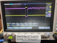
Looking at the MOSI signal from the display board, it has some noise on it before it goes through the 74LS14. I'm attaching the signal before the 74LS14 and after. Does this look correct ...? It is inverted as expected, but should the noise cause the output to move like that? And the MISO signal from the keyboard has a ton of noise on it.
99% of the time I'm still getting "error 18", which means a bad DOC II chip. 1% of the time though, it will boot past this. I can navigate menus, etc. After a bit, it crashes with "error 145", which is "unknown sampling interrupt". So I would think that either the 68k can't talk to the DOC II properly, or the DOC II is indeed faulty.
One other interesting thing I've noticed is the display will sometimes have repeated characters. "ERRROR 18", etc. So I began looking into the communication between the main board, the keyboard, and the display board.
The display board schematic is here: https://drive.google.com/file/d/1Xanhqlr2VQBKGBqwTZiHOqU8fAepFDyP/edit
Looking at the MOSI signal from the display board, it has some noise on it before it goes through the 74LS14. I'm attaching the signal before the 74LS14 and after. Does this look correct ...? It is inverted as expected, but should the noise cause the output to move like that? And the MISO signal from the keyboard has a ton of noise on it.
I haven't gone back and reread the whole thread, but have you resoldered the DOC II chip's pins (or those of its socket)? Have you checked the caps in the power supply? Are any of those leaking? Is there noise on the power supply rails?
Hi cruff. Yes, I've resoldered the socket of the DOC II and cleaned the socket with deoxit spray. PSU is recapped. All electrolytics on main board (other than some on the analog section) replaced. All caps on display board replaced. 20 pin ribbon cable to keyboard replaced. 20 pin headers on both sides replaced. Cable going to display board cleaned. Seems fine.I haven't gone back and reread the whole thread, but have you resoldered the DOC II chip's pins (or those of its socket)? Have you checked the caps in the power supply? Are any of those leaking? Is there noise on the power supply rails?
I did a lot of work to the board where the ram is in the past. Replaced all ram chips that tested bad. Tested a ton of the ceramic caps on the main board, none are ever bad.
There has to be something wrong with the communication between the main board, keyboard board, and display board for the characters to repeat like they do on occasion. Does the output of the 74ls14 look correct? I thought it would ignore the noise. Thought that was the point of using it.
The voltage levels on the output of the 74LS14 don't look right, they should not go negative unless the ground of the scope probe wasn't really at ground like the trace on the input side. Also that low to high signal transition isn't good. Can your replace the 74LS14?
Yeah, I tried replacing it the other day. Output looked the same.
Scope ground was connected to the same ground that I took the input reading with. I'll double check it tomorrow though.
This signal goes to the keyboard board. Still haven't found a schematic of it, but it's not crazy complicated. The bypass caps on it tested fine. I cleaned all sockets on it as well.
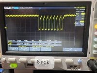
Is C12 good? What does the BSCK signal look like at pin 8 of the 74LS14? Is there any voltage differential between GND at pin 7 and the GND at pins 1 and 4 of connector J1 where power is fed to the display board? Is the keyboard that you had disconnected the button matrix at the bottom of the schematic? And can you get a dual trace capture of the input at pin 11 along with the output at pin 10?
C12 is good - everything on the display board was recapped the other day.
No voltage differential between ground on the chip and 1 and 4 on j1.
The button matrix is built into the display board. Keyboard is a separate board. Signals go to J2 to the main board and directly to another cable that goes to the keyboard board. Other than clk, which does come from the DOC II on the main board
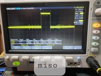
Also attaching the MISO signal from the keyboard.
No voltage differential between ground on the chip and 1 and 4 on j1.
The button matrix is built into the display board. Keyboard is a separate board. Signals go to J2 to the main board and directly to another cable that goes to the keyboard board. Other than clk, which does come from the DOC II on the main board
Also attaching the MISO signal from the keyboard.