• Please review our updated Terms and Rules here

Fixing a Sol-20

I have done some voltage reading suggested by dave_m on the 9216 masked ROM to try to determine what the exact pinouts are. I took reading from pins 18 through 21. I measured Pins 20 and 18 both from the 9216 and also with the 9216 removed from the socket:

Pin 21: ~4.73V
Pin 20: ~4.2V (fluctuates between 4.1V and 4.4V)
Pin 20 (from the socket. 9216 removed): ~4.2V (fluctuates between 4.1V and 4.4V)
Pin 19: ~11.96V
Pin 18: ~27.3mV
Pin 18 (from the socket. 9216 removed): ~7.9mV

While I was at it I took the power readings from the main power connector on the motherboard coming off the PSU

Pin 1: GND (and where I took my GND line from)
Pin 2: 4.92V
Pin 3: -11.74
Pin 4: 11.96
(these are listed in the SOL-20 manual as +5V+5%, -l2V+5%, and +l2V+5%)
 
Hi gubbish,
Yes, pin 20 seems to move around quite a lot...at least on my digital meter it is anywhere between 4.1V and 4.4V and is moves around rapidly.

Nama,
It looks like one of the enables is always low (pin 18 ) and the other pulses low (pin 20). Do you have a schematic to double check?
-Dave

dave_m thinks that pin 20 pulses low which would probably make sense with that voltage reading, but I'm not sure exactly why a chip enable line would pulse at all. I thought it was either on or off.

As for pin 18, I'm not sure what would cause the different readings.
 
dave_m thinks that pin 20 pulses low which would probably make sense with that voltage reading, but I'm not sure exactly why a chip enable line would pulse at all. I thought it was either on or off.

It only pulses low (usually low == chip enabled) when the chip is being addressed through address decode circuitry. Normally, you compare the top n bits of the address to the value that represents the address you want the device to appear at, and pull /CE low when the address bus equals this value. Otherwise, it would appear at all memory locations.
 
Thanks glitch,
I think I understand it now.
So I guess the question is, can anything be assumed about the health of the the ROM by the fact that the chip enable line is pulsing? Maybe not. Basically the only thing on the screen at this time is the flashing cursor, no prompt.
 
I hooked up the simple 2716 adaptor to replace the 9216 (See: http://www.vintage-computer.com/vcforum/showthread.php?25821-Processor-Technology-SOLOS-1-ROM), and this time I was able to actually get the cursor on screen, the same as with the 9216 ROM. One assumption I can take away from this is that the original 9216 ROM is probably ok.

I may still be dealing with a bus conflict as glitch mentioned previously, but I won't know for sure until the new RAM arrives. In the mean time I may pull out the trusty logic probe and have a poke around. Any suggestions where I should start looking?

Cheers
 
Some great news. I returned from work to a package of RAM waiting for me. I immediately installed it into the machine, and now I get the prompt and a flashing cursor...YAY!!!!!
The keyboard is totally dead as I suspected, but I was able to manually short some of the keys on the solder side of the keyboard and charachter do indeed appear on the screen, so it looks like the keyboard logic is working. I have a stack of foam keypads that I'll install soon and hopefully I'll have a fully working machine.

Thanks for all the people who have contributed and help me on this thread. I won't say I'm a 100% done yet, so you may see me back here again soon with some more question.

Awesome!
 
Thanks gubbish, thanks Tezza.
Yeah it actually had me a little worried. The rarer the computer the harder it is to find parts and people who are willing to put their personal time into helping...so again, a huge THANKS to everyone.
 
Do you have pictures of the RAM / what socket had the bad RAM? I have very similar voltage readings, wonder if I have the same exact problem!?? What a coincidence. I admit that I stopped once I took the readings, I have not pursued repairs. I already have the foam replacement for the keyboard, I hope to get in there again soon.
Bill
 
I can put some pictures of the old RAM and the new RAM up on my page if you like? The original RAM is labeled 21021PC and the new RAM is 2102L1PC.
Exactly what position the bad RAM was in was not noted. Basically I pulled all the user RAM and removed the first chip of the video RAM. then one by one I put the user RAM into the empty socket of the video RAM. If the 09090909 pattern changed in any way then I considered that RAM bad and put it to one side. I found 3 bad RAM this way. Sometimes the change of pattern was easy to spot (e.g.080808080...) but other times it wasn't so easy as the screen would still mostly be 090909 but one small section may be different.

I just did the keyboard foam replacement for my machine. The original foam pads just fell apart like dust. I was actually just one foam pad short of doing all the keys, but Tezza has offered to send me one of his spares for a trade on a couple of 2716 EPROMs. He has just a couple left over from a recent Apple Lisa keyboard fix...Thanks Terry.
The actual keyboard fix was easy as I didn't have to make the pads, it just took a little time pulling out all the old foam pads, maybe an hour and a half from start to finish.

I've recently been busy converting .ent files to .wav files for the SOL-20. I hooked up a serial connection from my Macbook Pro (using a Keyspan USB serial adaptor) to the SOL and transfered the programs using zterm on OS X. I then saved them out from the SOL and recorded them on my Macbook Pro as a .wav file...simple in the end, but it took me ages to figure out how to get the serial connection working. The problem turned out to be a faulty serial cable...hate that!

Let me know if you need to see pics of the RAM and I'll see if I can't get those up when I get home later.
 
Last edited:
thanks. I was curious *which* slots had the bad RAM, but this weekend if I have time I will swap out some of the 2102's and see how it goes.
 
After the recent fix I have been using the computer heavily. Firstly, I have been creating a library of .wav files by transferring the .ent files to the Sol via a serial connection to my Macbook Pro and saving them back out again. And secondly to do burn-in testing on the machine. I think the last time it was turned on was over 20 years ago so if something else was going to fail, I wanted to know about it sooner rather than later.

I powered up the Sol-20 today only to be greeted by two flashing cursors on the screen. The first cursor was where it should be, one character to the right of the prompt, but the second cursor was offset by another 8 characters. If I entered text via the keyboard both cursors would move. After 8 characters were entered the phantom cursor would then jump 8 characters behind the real cursor. With another 8 characters entered the phantom cursor would jump infront of the real cursor again…

Sol-20 double cursor.jpg

See the video here:
http://web.mac.com/lord_philip/other_computers/SOL-20.html#15

I quickly scanned through the Sol-20 theory of operation manual and came across something that seemed interesting:

"Seven-bit ASCII-coded data is written into RAM chips U14
through U20 from bits DIO0-6 of the Bidirectional Data Bus, and the
cursor bit (DIO7) is written into RAM chip U21."

I had previously had problems with flakey RAM, so U21 could indeed be a possible culprit. I quickly pulled it out and replaced it with a known working RAM chip...Problem solved. Too easy!
 
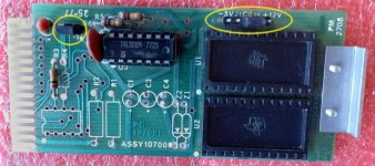
While working on restoration of my Sol-20, I've run across this thread a few times while doing searches about the personality module. For the sake of those who find this thread in the future, I'm adding additional information about the PM-2708 Personality Module and using it with 2716 EPROMs.

The PM-2708 module can be configured to work with a 9216 ROM (2K), an 8316 ROM (2K), a 2716 EPROM (2K) (and therefore 1/2 of a 2372 can be used as well), or two 2708 EPROMs (1K each). The most common configuration, and the default jumper settings on the board (PCB traces present), is for the 9216 ROM.

These ROMs and EPROMs are not directly interchangeable on the board without changing jumpers to accommodate the differences in pin assignments and power supply requirements as shown in the table below:

jumpers.jpg

To make the board easy to use for any of the above combinations, I cut the default jumper traces on the PCB (-16, C0 to 21, 19 to +12v) and installed header pins in each jumper position. This allows use of standard push-on jumpers to select different options. Note that using 2708’s requires installation of the parts missing on the PCB shown below in order to generate –5v for the the 2708’s.

Personality Module 2708.jpg
 
Last edited:
Back
Top