• Please review our updated Terms and Rules here

Flight 68K Issue 2. What can I do with it?

Stephen Scutt

Member
Joined
Sep 9, 2015
Messages
22
kaycomp2qk4.jpg

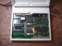
Hi all. As well as acquiring a Micro Professor Z80 trainer recently, I also got a Flight 68K trainer board. It is the issue shown in the picture.
I'm not sure how to connect it up to anything to get it working.
Also, there is scant information on this particular issue on the web.
Please would anyone know what I would need to use this board? I see it has parallel ports whereas the models I see on the web have serial type ports...
If anyone knows of a link to the manual in PDF I would also be grateful.
Thanks,
Steve.S.:D
 
I don't see any parallel ports but I do see what could be two serial ports. Parallel ports are female; serial ports are male, usually.
 
I think your model just has bigger connectors.

You should be able to identify the RS-232 line drivers, and the DUART datasheet is available, so figuring out how to connect a terminal (basically, whether the Flight-68K is DTE or DCE) should be easy.

What can you do with it? Well, it's a trainer, you can learn how the 68000 works :)
 
searching on

"flight 68k user manual"

gives lots of hits. However most of the manuals I find are just the base user guide, but there are some others. I think what you really need is the matching software. It looks like it came with an Assembler and "C" compiler. I think the first plan would be to get power on the board, connect a PC running Hyperterm and seeing if there is any help in the on-board monitor...
 
Oh marvellous. Thanks everyone for the info and the heads up. I'd completely forgotten how the 25 pin connectors looked!
So I need to get hold of a 25 pin to USB serial cable.
Or would it be possible to wire up the Serial ports to a Serial to USB device? Or even the Arduino Serial Tx and Rx pins?
 
If you have a 9-pin adaptor you can get 9-25 pin adaptors on e-bay, but you may need to make a NULL Modem lead depending on how the ports on the Flight are wired (DCE/DTE).

The serial ports on Arduino and PI are 5v or 3.3 v so you would possibly need a level converter....
 
Hi g4ugm. OK, well I've tried a couple of things. First I have a 9 pin Serial male to USB cable which I use with my Atmel STK500 board anTTL tod I've tried connecting it up via wires to the pins of the Flight board (tx to rx, rx to tx and GND --NULL modem style). Opened Realterm but am not having much joy. If I unplug the board and plug it back in again,Realterm displays a dot or random character but thats about it. hmmm... Also I can't believe I can't find the PROPER user manual online... :(
 
excuse me if I am being pretty basic...

First thing I would do is check that you are using the correct ground on the 25pin. You need the ground on Pin-7 (signal GND) not pin-1 (protective ground)
Then make sure Realterm is configured for "No Flow Control".

If that does not fix things check which pins on the ports are transmitting data and which are sending data. If you have a meter set it on a range of 15V or more , put the Positive +VE lead on GND and use the -ve to see if there is a voltage on pin 2 or 3 on the DB25. Repeat with the DB9 (again 2 and 3) and then connect the pin with a voltage on the DB25 to the one without on the DB9.

You may also have to loop the RTS/CTS DTR/DCE/CD and on the DB25. Loop 4 + 5 and 6+8+20
 
I know this is an old thread but did you find the user manual as PDF ? (just acquired a 68k trainer MK2 myself)
 
Found this at http://documents.mx/documents/lab-2-interface-lab.html

may help a little ?

Lab 2: Simple I/O 1. Objectives - Interfacing a simple Input/Output application with the 68-K Flight Kit 2. Prerequisites - Some readings are required to cover the following: o MC68000 datasheet overview o PI/T datasheet readings o 68-K Flight Kit user manual 3. Description - After realizing the concept of microprocessor interfacing on preimplemented applications, it’s the time to build your own applications. - This lab’s application is very simple to implement. The task is to interface the 68K system with DIP switches for input and LEDs for output - The 68K processor should continuously read the value fed by the DIP switches, modifies it by swapping the least nibble with the upper nibble, and displaying the result in hexadecimal on the screen and on the LEDs - Each switch and LED should be prepared as follows: Lab2 4. Components, Devices, and Tools DIP switches 8 LEDs Resisters (330Ω, 4.7KΩ) The Flight-68K board Serial Cable A DB-25 to DB-9 converter 5. Lab Work - Setup your DIP switches and LEDS and connect them to the 68K system’s PIT. - Load your code into the RAM module - Run your application 6. Questions 1. 2. 3. Does your application need de-bouncer circuits? Give an example which de -bouncing is vital. Write a code that makes the processor reads the switches only when the character "@" keyboard button is stroked. Hint: use the subroutine implemented in the ROM Normally, outputting results to LEDs is done through latches. Here we didn’t use any latches; Why? Lab2


then from http://www.dca.fee.unicamp.br/courses/EA877/1s1997/68K/in-out.html

Inputting data from the keyboard and outputting results to the screen are handled by Monitor Systems Calls written in by the programmer. They are made by executing a "trap #11" instruction and a .byte word indicating the call. The full list of system calls can be found in the Flight-68k Users Manual but some of the most useful ones will be looked at in this section.
 
Thanks for the links.


Alas the holy grail seems to be: Flight-68k Users Manual

Looking for info on the jumpers next to the (EP)ROM/RAM sockets, memory mapping, pinout of the expansion connector and such.
 
flite.co.uk still exist and will sell you a user manual for, I think, about £70. I didn't think it was on to copy my manual.
 
The Kaycomp 68000 board was a constructional article in Wireless World magazine over 2 or 3 issues, cannot remember what year though.
I believe it is the same as the flight 68k trainer.
 
Hiya. I got sent a copy from Flite electronics in the UK! I'm in the process of scanning it so watch this space: :)
Hello! I bought one of these on ebay, it's in immaculate condition, but... the manual in in French :) Did you ever scan the manual? Also my copy is missing 10 pages at the back which should be the circuit diagram , for some reason.
Cheers,
Con
 
I'm looking for it, I have not it yet.
BTW what's interesting me are exactly those missing 10 pages... i.e. the schematic diagram...

delo
 
Back
Top