gsteemso
Experienced Member
Hi all!
Just retrieved the rest of my retrocomputing collection from my parents' place in Canada, and was delighted to discover that the PET still works. On examination, it has something to the effect of "80 column mainboard" written on the PCB, but it only shows a Fat 40 screen. (Apparently, at least -- Jim Butterfield's machine language book says you can distinguish a Fat 40 from a regular 40 by the way the cursor keys autorepeat. This one's do, so...)
The ROMs are in 5 chips. One is socketed and the others are not; the socketed one has a different part number than the others. (The soldered-on ones are 901465-20 through 901465-23; the socketed one is 901499-01.) There are also two sockets for user ROMS; one is empty and the other contains an unlabelled mystery EPROM with the window taped over. What's up with the socketed system ROM not matching the other four? Is there any way to tell what's on the user-ROM thingy?
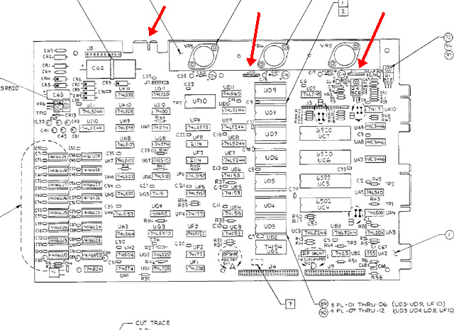
This thing has a ridiculous number of jumper posts and expansion headers in it. There are two unpopulated jumper post sockets, two 50-pin ribbon cable connections which appear to be for system expansion of some description, the user-port, IEEE-488 and cassette-port edge connectors along the back of the board, and what appears to be a SECOND cassette edge connector on the right-hand side of the board near the usual one in the back corner. The two 50-pin headers and the, apparently, second cassette connector are behind a metal plate screwed to the case. What can I connect to all of these things and is there any reason to bother? I understand I can update the thing to 80 columns by closing some jumpers. Which ones and what else do I need to do?
Any help or advice you may offer would be gratefully received!
Just retrieved the rest of my retrocomputing collection from my parents' place in Canada, and was delighted to discover that the PET still works. On examination, it has something to the effect of "80 column mainboard" written on the PCB, but it only shows a Fat 40 screen. (Apparently, at least -- Jim Butterfield's machine language book says you can distinguish a Fat 40 from a regular 40 by the way the cursor keys autorepeat. This one's do, so...)
The ROMs are in 5 chips. One is socketed and the others are not; the socketed one has a different part number than the others. (The soldered-on ones are 901465-20 through 901465-23; the socketed one is 901499-01.) There are also two sockets for user ROMS; one is empty and the other contains an unlabelled mystery EPROM with the window taped over. What's up with the socketed system ROM not matching the other four? Is there any way to tell what's on the user-ROM thingy?
This thing has a ridiculous number of jumper posts and expansion headers in it. There are two unpopulated jumper post sockets, two 50-pin ribbon cable connections which appear to be for system expansion of some description, the user-port, IEEE-488 and cassette-port edge connectors along the back of the board, and what appears to be a SECOND cassette edge connector on the right-hand side of the board near the usual one in the back corner. The two 50-pin headers and the, apparently, second cassette connector are behind a metal plate screwed to the case. What can I connect to all of these things and is there any reason to bother? I understand I can update the thing to 80 columns by closing some jumpers. Which ones and what else do I need to do?
Any help or advice you may offer would be gratefully received!
")
 OKE193,start_lo