• Please review our updated Terms and Rules here

History and start of life of my strange 11/45

Activmaker

Experienced Member
Joined
Apr 3, 2018
Messages
66
Location
Paris, France
Hi,

In 1995 during learning session, I discovered PDP-11 architecture and programmation. I liked it a lot. Since few years now , I search to get my own PDP. I wanted a unibus machine not Qbus. A 11/70 or 11/45 would have been perfect , but I didn't find something interesting. Last year I thought :"Is it possbile to build one from scratch ?". So, I start to read and read and read again DEC documentation (Thanks to bitsavers guys !) . I also learned to make PCB boards and re-learned electronic (I learned basic electronique around 1988 ). Around july 2018 , I decide to really start the study. I choose 11/45 for 2 reasons:
1) 11/70 is a little bit complex fo me.
2) I like the concept of Unibus B in 11/45.

My goal is to keep the "spirit" of PDP11. Mes requirements are :
1-My boards must be run into a real PDP.
2-My PDP can use boards of real PDP.

I studied an hardware architecture and finnaly I decided to have (for the first "shoot") this backplane architecture :

Screen Shot 04-19-19 at 08.49 PM.jpg

Today I plan to use a brige between row 2 and row 3 to use dual port memory.

The actual state of this project is
1 M930 and 1 M9302
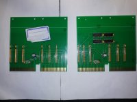
terminators.jpg

1 Test board for SPC . The board helped me to debug wrapping of backplane. I use it to visualize the signals and put an logical analyzer.

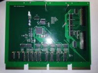
1 CPU Board (Will emulate KB11A +MMU+FP). On right part there is 2 connectors for the console. Switch on board can activate or not some parts (MMU/FP/M9312). CPU can use external LTC signal or use an internal clock. An connector is present to connect a USB terminal (MobaXterm in my case) . Not in the "spirit" of PDP 11 :).


cpu.jpg

Few G227 Boards.
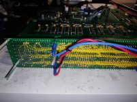
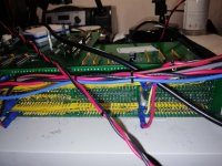
Of course a backplane has been made.
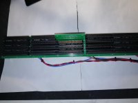
backplane1.jpgbackplane2.jpgbackplane3.jpg

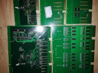
All boards:

allboards.jpg

On the top left the memory board with 128Kw. Some bugs was found in it , I modified PCB routing using wiring and cutter !.

An other small board has been made to filter the power supply, give a 3.3v and simulate sequence of ACLO and DCLO.
Terminators,bus control,Memory board seems to works correctly. CPU Test are not finished yet but as far as now all tested parts work.

Today I decided to show you this year of work.
And now ? Of course I will ontinue on it, I already know that I will make a new CPU board ,but this one will ge me a lot of work!. I am studying also a RL11 SPC board (With 4 emulated RL02).
I let you to comment this project maybe you like , maybe not...
Thank you for reading me to the end
 
So do you have an 11/45 running on your FPGA (what is it by the way, the photo resolution is too low) in simulation?
 
No, system is not yet operational. When I say “Start of life”, it means , power on. Until today I mainly worked on hardware part. At this day 95% of hardware has been tested.
This week end , I checked signal integrity through backplane. it look goods but with some cross-talk between MSYN and SSYN.
I also started to write some code to test DATI/DATO operations. Seems ok with time cycle around 250/350 ns (Tested with my 128kword board). Test was intensive to detect corrupt signals between CPU and memory. No issues found.

I didn’t use FPGA for 2 reasons :
1) When I started this project , my electronic knowledges was not strong enough to start with FPGA. Now, I am thinking about it.
2) My objective was not absolute performance. I hope to obtain something near the real machine. I am not looking for something 5x faster than original.

I need to also work on a SCP board to have ‘somebody to talk with’ :) . My goal is a to have an RL11 emulator. But if someone agrees to lend me one, I'm not against :).
I will start development in few hours, some parts in DEC documentation are not clear for me , so I will need help to do the job properly.
Thanks.
 
My bad, I was guessing it was an FPGA. Could not read the parts marking. What CPU is it?

You might want to look at the SIMH simulator: https://github.com/simh/simh in PDP11/pdp11_cpu.c to give you a head start on the complexity of a full PDP-11 CPU design.
 
That is really fantastic work! To me the DD11 backplane PCB is especially interesting, I'm sure there would be a market to sell a few repop's of those.
 
Thanks for the comment. I have a lot of works to finish this project !
AK6DN, the mainboard use a MCU with an ARM core running at 102 Mhz. To be honest, I am not sure it will powerfull enough to simulate all parts . Yes I know SIMH , and I already read and analyse many DEC documentations around KB11A and 11/45 . I am sure to have work for at least 1 more year ! :p
 
Very impressive work.
And having the emultaed 11/45 on a single board which would directly go into a DD11-CK (or -DK) would certainly avoid the requirement of an oriignal backplane.
It would be great to see your board talking to existing devices like a DZ-11, or an RL02, or even an RK05.

Are you also planning to have your mainboard be equipped with the 256Kb memory in a later revision of it?
 
having the emultaed 11/45 on a single board which would directly go into a DD11-CK (or -DK)
Yes, you are right, at the very first part of the study I tought like you, but with fast bus and unibus B it is not the same story.

It would be great to see your board talking to existing devices like a DZ-11, or an RL02, or even an RK05
Oh yes !. If I bring my part to you, can we test with your boards ? ;) I will also like to connect my boards on the real 11/45 console, I respected the pinout on J1/J2.

Are you also planning to have your mainboard be equipped with the 256Kb memory in a later revision of it?
Not sure to understand , but today I already have a 256Kb memory board compatible Unibus or MUD. I am working on a revision to remove some bugs in the actual memory board, but this revision will be independant and should be compatible with other Unibus system.
 
What are you using for Unibus driver chips? IIRC, the signal requirements are a little bit mismatched for modern driver chips that are readily available.
 
I mainly used 74LS642-1 . The -1 is important, 74LS642 is not ok . Before choose it , I made tests with few other. I found that it is near the requirements. Datasheet have big margin and you can think this chip is not adapted. But I decided to test in an unibus condition (Small 8 bits bus) and take measurements.
Regarding threshold I got these values :
vih=Around 1,60
vil =Around 1,30
I was not able to check the input curent. My instruments do not detect something <100µA . Look like good.
Vol is around 300mV.
Signals are good at scope, the square are without under/overshoot.
Feel free to comment this and give your opinion.
 
Thanks for the tip, I will have to look into this one. What pullups do you use on the device side? As I understand the 74LS642 are open collector on both buses.

I'm currently looking for alternatives to the DC005 (aka Signetics C2324N) and the biggest challenge is to find receivers with the right thresholds. Currently I'm using a combination of 74F38 and 74HC4049, the 74HC4049 are powered with a 3.3V to achieve the typical 1.7V threshold. I'm also considering to test the AM26S10C as they are still on stock and cheap. They have a threshold of about 2V. Which is slightly too high. Did you test or consider these as well

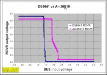
Here's a plot I did of 26S10 vs 8641 bus threshold: 26S10vs8641.jpg

Besides the 26S10 threshold being about 500mV higher it also has a much faster edge rate than the 8641, so ringing on transitions will be more of an issue.

The 74LSX64x is better matched to the 8641 in terms of edge rate/propagation delay. I suspect the '642 will work ok in small single backplane systems but will have issues in larger backplanes and/or driving the standard UNIBUS cables.

Alas there really is no good replacement solution for the venerable 8641.
 
Is ringing in small Q-Bus (in my case) backplanes with proper termination really an issue? I have looked at the specs. Propagation delay is not too different, not even factor 2, and definitively not causing an issue. However I did not find any figures for the transition time of the DS8641 or DC005/C2324?
Actually I'm more concerned of the threshold. Both the 26S10 and the 74LS64x have not the optimal threshold of 1.7V. Each is equally off. So what is less critical, if the threshold is lower or higher?
 
Hi,
What pullups do you use on the device side? As I understand the 74LS642 are open collector on both buses.

I use small pull-up (150 Ohms). With greater values signal becomes rounded.


I suspect the '642 will work ok in small single backplane systems but will have issues in larger backplanes and/or driving the standard UNIBUS cables.

What kind of signals can I expect on large backplane ? . I suppose to have a lot ringing , cross talking..Do you some signal capture or link about this ? Hysteresis of 74LS64x seems not to be a good point for noise , right ?
 
Is ringing in small Q-Bus (in my case) backplanes with proper termination really an issue? I have looked at the specs. Propagation delay is not too different, not even factor 2, and definitively not causing an issue. However I did not find any figures for the transition time of the DS8641 or DC005/C2324?
Actually I'm more concerned of the threshold. Both the 26S10 and the 74LS64x have not the optimal threshold of 1.7V. Each is equally off. So what is less critical, if the threshold is lower or higher?

QBUS single backplane, ringing is not a significant issue. Ditto for a single UNIBUS backplane. However, when you start using multiple UNIBUS backplanes the jumper and cable transitions cause multiple impedance discontinuities/signal reflections/ringing. This is where the slower edge rate of the 8641 helps; less of a reflection on a discontinuity. Also the 1.5V switching threshold when using 180/390 dual termination minimizes the effect of any ringing, on both the rising and falling transitions.

Usually ringing on the falling (assertion) edge is more critical as the edge is actively driven by the driver, and the switching margin is lower. The rising edge is passively pulled high by the dual end 180ohm pullups when the open collector driver turns off. So a 1.7-2.0V threshold is going to be better than a 1.0-1.3V threshold.
 
Nothing is perfect, except if you have some DC005 on stock :D. Looking for the 74LS642 I found them rather expensive, even more expensive than two DC005. And the SMD version seems no longer to be available. Also the fact that the device side is as well open collector requires a lot of pull ups which consume quite some power. Difficult to say which path I will go. I still have my own solution using 74HC4049 and 74S38 which has its own drawback.
 
Here my comments. First on the 74LS642-1. It‘s input levels are just LSTTL and also the input current is standard LSTTL. Also the requirement that the inputs must be floating when the card has no power is not the case. In the case you have only a few cards and you can make sure that all cards are powered equally, e.g. single Chassis, they can be used, for a small bus all these factors are not critical. The TESLA chips are an option, but so are the NOS C2324N. So as long as you build cards and mix them with original cards in single backplane environment you can pretty much use everything which has an open collector output that can sink 48mA.
 
Back
Top