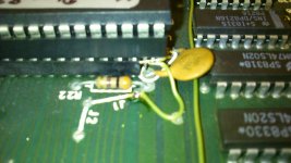
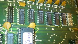
The modifications are tested on an 81-240A mainboard
The 81-240 mainboard has a ROM socket for up to 2732 EPROMs.
The KayPlus83 ROM is an 2764 EPROM. I use a ATMEL 28C64B EEPROM with success.
The original ROM socket missed the A12B line and the /ROMCE selects only 1K of ROM space.
So you have to change some minor things:
You are now ready to power up the Kaypro and boot it with the modified floppy disk.
After the above modification you are able to use also the original Kaypro EPROM (e.g. 81-232) in the socket.
Have fun!
For the 81-110 mainboard the changes are similar, you also have to isolate pin 21 of U47 from +5V and connect the pin 21 of U47 with the A11B signal from e.g. U33 pin 6.


The 81-240 mainboard has a ROM socket for up to 2732 EPROMs.
The KayPlus83 ROM is an 2764 EPROM. I use a ATMEL 28C64B EEPROM with success.
The original ROM socket missed the A12B line and the /ROMCE selects only 1K of ROM space.
So you have to change some minor things:
- First follow the instructions which are supplied by MICROCode Consulting to build a KayPlus boot disk, which is compatible with the new KayPlus83 ROM.
- Then remove the old EPROM from socket U47 and desolder U80 ( 74LS08 ).
- Cut the trace under U80 between GND and pin 9 to free the AND gate (pin 8,9,10).
- Solder in an 14 pin socket. Plug in the 74LS08.
- Cut the trace from U60 pin 15 to U47 pin 18.
- Route an wire from U80 pin 8 to U47 pin 18.
- Route an wire from U80 pin 9 to U60 pin 14.
- Route an wire from U80 pin 10 to U60 pin 15.
- On an 28 pin socket connect pin 1 with pin 27 and pin 28 and a 1" long wire.
- On pin 2 of the socket connect a 6" long wire.
- Plug the 28 pin socket into the socket of U47, so that the pins 1,2,27 and 28 hangs over.
- Connect the wire which comes from pin 1, 27 and 28 of the 28 pin socket to +5V.
- Connect the wire which comes from pin 2 of the 28 pin socket to U33 pin 3.
- Plug in the 2764 or 28C64B with the Kayplus83 data into the 28 pin socket, that is plugged in the socket from U47.
You are now ready to power up the Kaypro and boot it with the modified floppy disk.
After the above modification you are able to use also the original Kaypro EPROM (e.g. 81-232) in the socket.
Have fun!
For the 81-110 mainboard the changes are similar, you also have to isolate pin 21 of U47 from +5V and connect the pin 21 of U47 with the A11B signal from e.g. U33 pin 6.


Last edited:
