Mochatea396
Experienced Member
Hello members,
I have an A2S4000 iic that I only get the green led on the keyboard. Here’s the history up to now. When I got it, it booted. The board had already been modified for ROM0 so I burned a 4X ROM. I was using it running diagnostics and playing all kinds of games. Passed the onboard “system ok” many times. Then it started locking up, messed up video. The onboard now was giving me ram errors. Different errors every time I’d run it. Then I’d get a system ok and the machine would boot again. Would be fine for a little while and then do it again. Then one day it just stopped booting altogether and just the green led.
What’s been done:
The PSU (internal and external) are good.
I replaced the CPU, MMU, IOU with known working chips, as well as tried the originals in a working machine. All good.
I replaced the sockets on the CPU, MMU and the monitor. (Nice removals with a gun no damage)
I socketed the 311 and the 555 and those tested good as well.
I socketed all 16 ram and replaced them with known working chips. The others all tested fine in another machine.
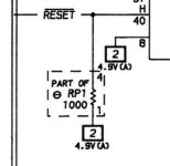
I’m getting no logic reading at all from pin 40 on the CPU on boot. I am however getting 5v to the correct pins on the CPU, MMU, IOU and the monitor. 5v to the 555, IWM, TMG, GLU and the AY3600 as well. I was getting 15.3v to the LM311 which I think may be normal. CR2,CR3 tested ok in circuit, CR1 has to be removed to test and I didn’t. I’m getting the correct ohms on the resistor networks that SAMs says I should. And all 16 RAM show 5v. Strangely any pinout for 4164 ram I could find online the GND and the VCC are on different pins than I’m getting. Even on a working machine they don’t match what I found online. They match the board I’m working on. This board also has the factory mod replacing the LS161 with the oscillating crystal.
Any direction would be appreciated

I have an A2S4000 iic that I only get the green led on the keyboard. Here’s the history up to now. When I got it, it booted. The board had already been modified for ROM0 so I burned a 4X ROM. I was using it running diagnostics and playing all kinds of games. Passed the onboard “system ok” many times. Then it started locking up, messed up video. The onboard now was giving me ram errors. Different errors every time I’d run it. Then I’d get a system ok and the machine would boot again. Would be fine for a little while and then do it again. Then one day it just stopped booting altogether and just the green led.
What’s been done:
The PSU (internal and external) are good.
I replaced the CPU, MMU, IOU with known working chips, as well as tried the originals in a working machine. All good.
I replaced the sockets on the CPU, MMU and the monitor. (Nice removals with a gun no damage)
I socketed the 311 and the 555 and those tested good as well.
I socketed all 16 ram and replaced them with known working chips. The others all tested fine in another machine.
I’m getting no logic reading at all from pin 40 on the CPU on boot. I am however getting 5v to the correct pins on the CPU, MMU, IOU and the monitor. 5v to the 555, IWM, TMG, GLU and the AY3600 as well. I was getting 15.3v to the LM311 which I think may be normal. CR2,CR3 tested ok in circuit, CR1 has to be removed to test and I didn’t. I’m getting the correct ohms on the resistor networks that SAMs says I should. And all 16 RAM show 5v. Strangely any pinout for 4164 ram I could find online the GND and the VCC are on different pins than I’m getting. Even on a working machine they don’t match what I found online. They match the board I’m working on. This board also has the factory mod replacing the LS161 with the oscillating crystal.
Any direction would be appreciated
 But using the correct pins 8 and 16 I’m getting 4.99v on the money on all 16 ram. Those must have been the pins I was using before and not marching that incorrect info was boggling me. Ok, so all ram as well as everything I’ve mentioned previously seem to be getting 5v where it should. I was kind of hoping there was going to be a problem there but the chase continues. Lead me to where I should be looking next.