inmbolmie
Member
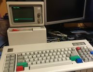
I have embarked on a silly quest to make this work:

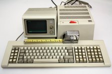
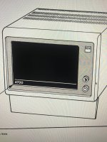
IBM 4704 banking terminal, I don't still have the (expensive) keyboard but that's not a concern as the protocol is pretty well documented and a converter could be made.
My worries are, in this order:
1 - Figure out the monitor pinout and make a cable as some s of a b cut it at some point.
2 - Fix the monitor as the VSYNC circuit looks pretty roasted and most likely won't work. Note that the monitor takes its power from the terminal so I cannot test it until I solve point 1.
3 - Figure out the local loop protocol to communicate with the terminal.
I'm now at point 1, and this is the situation. I'm not getting VSYNC/HSYNC at the terminal side int the output cables I have available, and I'm trying to figure out why. The monitor pinout is something like this, and should be similar to comtemporary systems like the displaywriter:
POWER: +15V(?) +5V(?) GND "ANOTHER GND" SHIELD
SIGNAL: "TTL VIDEO" "TTL VIDEO2" "VIDEO GND" HSYNC VSYNC
That is, 6 signals ignoring the grounds and shield.
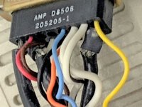
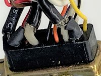
But at the terminal side, not counting the various grounds I have 9 power and signal cables:
POWER: +15V +5V ----> OK
SIGNAL: "TTL VIDEO" "TTL VIDEO2" orange black brown blue yellow
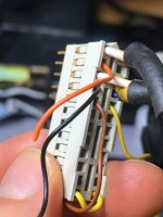
The cable colors mostly don't match with this on the monitor side.
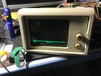
The terminal powers on and one of the video signals is indicating we have a working terminal, because it looks like a line at the bottom of the screen with text below. The video mode is apparently similar to CGA 00h but with chunkier characters (40x12 chars)
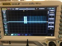
The uknown signals are showing:
If I had to bet anything at this point, black and yellow would be VSYNC and HSYNC with positive polarity, but they are not showing anything. I tried to put yellow and blue to ground and if I do that, brown goes low, but that's all, no change in any other signal.
This is the video card.
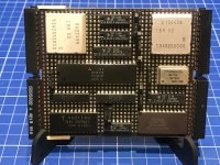
My bets for the components are:
The CRT controller seems to have the correct VSYNC and HSYNC signals (hooray) on pins 27 and 26, that are routed to the canned IBM chip next to the video connector. But those signals are not shown on the available cables cut from the original DA-15 connector cable.
If anyone here is familiarized with systems like this it would be nice to know if you have any idea of how to actually get VSYNC and HSYNC on the output cables, or better the actual connector pinout.
Plan B is routing VSYNC/HSYNC from the CRT controller to the cable using an extra 74LS244, and ignore all the unknown cables, but that is a risky business.

IBM 4704 banking terminal, I don't still have the (expensive) keyboard but that's not a concern as the protocol is pretty well documented and a converter could be made.
My worries are, in this order:
1 - Figure out the monitor pinout and make a cable as some s of a b cut it at some point.
2 - Fix the monitor as the VSYNC circuit looks pretty roasted and most likely won't work. Note that the monitor takes its power from the terminal so I cannot test it until I solve point 1.
3 - Figure out the local loop protocol to communicate with the terminal.
I'm now at point 1, and this is the situation. I'm not getting VSYNC/HSYNC at the terminal side int the output cables I have available, and I'm trying to figure out why. The monitor pinout is something like this, and should be similar to comtemporary systems like the displaywriter:
POWER: +15V(?) +5V(?) GND "ANOTHER GND" SHIELD
SIGNAL: "TTL VIDEO" "TTL VIDEO2" "VIDEO GND" HSYNC VSYNC
That is, 6 signals ignoring the grounds and shield.
But at the terminal side, not counting the various grounds I have 9 power and signal cables:
POWER: +15V +5V ----> OK
SIGNAL: "TTL VIDEO" "TTL VIDEO2" orange black brown blue yellow

The cable colors mostly don't match with this on the monitor side.
The terminal powers on and one of the video signals is indicating we have a working terminal, because it looks like a line at the bottom of the screen with text below. The video mode is apparently similar to CGA 00h but with chunkier characters (40x12 chars)


The uknown signals are showing:
- yellow is an input floating high
- blue is an input floating high
- brown is an output high
- black is an output low
- yellow is an output low
If I had to bet anything at this point, black and yellow would be VSYNC and HSYNC with positive polarity, but they are not showing anything. I tried to put yellow and blue to ground and if I do that, brown goes low, but that's all, no change in any other signal.
This is the video card.

My bets for the components are:
- Center: some kind of CRT controller (definitely not a 6845).
- Bottom left: 2K video RAM
- Top left (canned): Character ROM (???)
- Top right (canned): video drivers (?)
- Bottom right: No idea, but the SLT-type connector next to it is apparently not used.
The CRT controller seems to have the correct VSYNC and HSYNC signals (hooray) on pins 27 and 26, that are routed to the canned IBM chip next to the video connector. But those signals are not shown on the available cables cut from the original DA-15 connector cable.
If anyone here is familiarized with systems like this it would be nice to know if you have any idea of how to actually get VSYNC and HSYNC on the output cables, or better the actual connector pinout.
Plan B is routing VSYNC/HSYNC from the CRT controller to the cable using an extra 74LS244, and ignore all the unknown cables, but that is a risky business.
Last edited:

