deanimator
Experienced Member
Hi all,
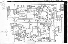
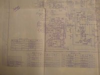
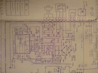
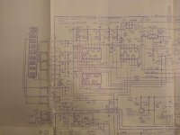
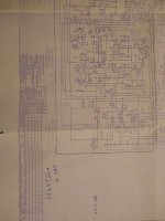
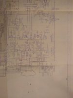
I'm currently awaiting one of these clunkers and I was wondering if anyone got a complete copy of the schematics, i.e. including its audio amplifier and power supply stage. There's some info on the Web which states that these monitors are internally similar to an IBM 5153, which has a PSU that works on both 120 and 230 volts AC with an automatic switchover. On the back-side of a 4863 though, there's only 120 volts AC input, which can make sense as I'm not sure if these machines ever made it over the pond.
In the PCjr technical reference, there's only a schematic of the guts driving the screen, which looks more-or-less identical to the schematic of a 5153.
I guess even if that thing lacks the dual voltage switchover, it could run with some series capacitive reactance straight from 230 volts... I won't tell anyone.") And since it's a direct-drive, I guess it doesn't matter if the mains AC is 50 or 60Hz since there will be some kind of a rectifier. If anyone could have a look that'd be greatly appreciated.
And since it's a direct-drive, I guess it doesn't matter if the mains AC is 50 or 60Hz since there will be some kind of a rectifier. If anyone could have a look that'd be greatly appreciated.
Thanks
I'm currently awaiting one of these clunkers and I was wondering if anyone got a complete copy of the schematics, i.e. including its audio amplifier and power supply stage. There's some info on the Web which states that these monitors are internally similar to an IBM 5153, which has a PSU that works on both 120 and 230 volts AC with an automatic switchover. On the back-side of a 4863 though, there's only 120 volts AC input, which can make sense as I'm not sure if these machines ever made it over the pond.
In the PCjr technical reference, there's only a schematic of the guts driving the screen, which looks more-or-less identical to the schematic of a 5153.
I guess even if that thing lacks the dual voltage switchover, it could run with some series capacitive reactance straight from 230 volts... I won't tell anyone.
And since it's a direct-drive, I guess it doesn't matter if the mains AC is 50 or 60Hz since there will be some kind of a rectifier. If anyone could have a look that'd be greatly appreciated.Thanks