• Please review our updated Terms and Rules here

IBM 5150 Model A - 120 to 220V PSU Conversion

inaxeon

Experienced Member
Joined
Jan 5, 2017
Messages
61
Heya folks

I live in the UK and I've got a 5150 Model A which has a black 120V PSU. I am quite keen to get it running from 220V without a step-down transformer.

I've spent the last few days studying the schematic and can see that is very likely possible. There very clearly is not any switch, jumper or even a set of fitting options to convert it but theoretically it looks possible.

Does anyone have even a photograph of the insides of the black 63W 220V supply? Did one even exist?
 
"Heya" back. Welcome to these forums.


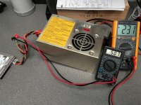
Mine is pictured at [here].

And I am pretty sure that a forum member here in Australia acquired one recently via eBay.


I have added your request to my to-do-list.


Thanks for the response.

From looking at the schematic it is clear that the 120V edition was designed with 230V operation in mind, and it seems possible that there is a variant of it out there which accepts 230V input. Quite possible that you may have one there. Question is what exactly are the differences. I suspect not very much...

Would definitely appreciate photos. If you are going to go to the hassle, start with the top of the PCB. I had quite a job removing the PCB from mine, and there is little point in you going to that length if it is fundamentally a different design!

Thanks!
 
Thanks for the response

From looking at the schematic I can see that the 120V edition was designed with 230V operation in mind. It seems quite possible that there is a variant out there which accepts 230V input. Quite possible, that is exactly what you have there. Question is what exactly are the differences, I suspect not much...

If you are going to take pictures - start with the inside "top" shot. I had quite a job getting the PCB out of mine. No point in you expending that effort if it is a fundamentally different design!

Thanks
 
"Heya" back. Welcome to these forums.


Mine is pictured at [here].

Apologies if I'm hijacking the thread, but that link makes for some interesting reading regarding my 5150. Mine seems to identify as an early 5150 (2 screws at back, lack of 'B' in circle, 16KB-64KB motherboard, black wide brackets on the expansion cards) but then there are signs it came a little bit after (silver PSU, second BIOS revision "5700671", TM100-2A floppy drives, plastic speaker holder). Interesting to see the little changes they made along the way.
 
I am quite keen to get it running from 220V without a step-down transformer.

It might be your lucky day. I had the same problem, a messy step-down transformer and knowing I (or someone) would eventually forget and blow it up.

After a couple of years thinking about it and studying the schematic, I designed a modification and updated my two (chrome) 120V 63.5W units a few months ago, and they now work fine at 230-240V. I've also fully documented the process including the engineering.

Post a photo of the inside so that I can see if it's the same PCB. You may have an AC fan which obviously would need to be replaced.

Yes, you are right that the primary DC portion of the circuit is wired as a voltage doubler and as such could run at 230 V under full wave rectification, but not the support components. I've never seen a schematic for the 240V unit so have no idea how that works, or even if it's the same concept.
 

Attachments

  • IMG_0219.jpg
    IMG_0219.jpg
    98 KB · Views: 3
Last edited:
I've also fully documented the process including the engineering.

Would certainly be good if you could share that.

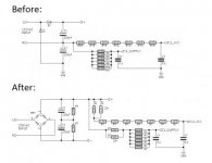
It's a work in progress, but I have attached my proposed changes so far. Perhaps you could compare that to your changes?

psu.jpg
 
Ok looks fairly easy, the front end of that schematic is a voltage doubler, to convert you can add 2 more diodes bridging the existing rectifier diodes and take the AC input that goes via the 2ohm 5w resistor and redirect it to the center of the 2 new diodes; creating a bridge rectifier and bypassing the doubler.

The issue is the feed to IC1 Pin 1 which seems to have 22.9v on it reduced by the string of resistors R69 -> R75, as long as the 2 capacitors are on spec they will act as a voltage divider and thus the output should be 120v, you may need to add some resistance back into that chain as its input is expecting 110v, it may not matter but I would start by replacing R75 the 750ohm with another 1.5K and check pin 1 for voltage and adjust as required.

Before you do anything just double check my thinking :)
 
Assuming it's the right schematic for the OP's PSU, May not be, Revisions etc.
 
Take a look back at page 1 of this thread. I am having to wait 24 hours for a moderator to approve each post! You were certainly heading in the same direction as me.

Additional changes I'd make is to replace the 2R resistor with an NTC matched to the bridge. Definitely going to be doing some experiments with it at 110V before I fire it up modified.
 
as long as the 2 capacitors are on spec they will act as a voltage divider and thus the output should be 120v

That is an interesting point. As you will see from my schematic I am operating under the assumption that it is no longer possible to draw current across C2 after a change to a full bridge.

But is that not the case? In a pure DC circuit you most certainly would not be able to, but I suppose the 100Hz output from the full bridge may allow this? The concern I had is that drawing current across C2 would lead to an increase in the voltage across C1, and potential explosion.
 
Perhaps you could compare that to your changes?
I can't read the values in that small image but it appears you have simply feed the IC and drive circuit off the approx 310V bus with increased resistance? Have you ascertained that the IC can withstand the exposure to the initial voltage before it drops due to current flow? Same with the drive circuit. Do you have a pic of the PS internals?
 
I can't read the values in that small image but it appears you have simply feed the IC and drive circuit off the approx 310V bus with increased resistance? Have you ascertained that the IC can withstand the exposure to the initial voltage before it drops due to current flow? Same with the drive circuit. Do you have a pic of the PS internals?

Did post a larger image previously, just need moderator to approve it...
 
Photo at [here].

I also pulled apart the silver version that I have. Photo at [here].

No need to warn me about the RIFA capacitors.

That looks almost exactly like mine. I can even see that it has some of the changes I have deduced.

If you could do a few more shots with the PCB out, from all four angles, and also a shot of the underside of it that would be absolutely fantastic.
 
Back
Top