• Please review our updated Terms and Rules here

IBM 5150 Power issues with P9 connector, RAM POST Error 201, Floppy issues

olegyk

Member
Joined
Apr 5, 2024
Messages
16
I recently acquired an IBM 5150 Type B (64K-256K), which on first couple of boots showed a POST error PARITY CHECK 2 (maybe with a 201 also).
But then the power supply went dead. I looked around a noticed the fan twitch on power on, so it looked like it going to over-current shut-down mode.
And indeed, when trying different cable unplugging combinations, it was found that diconneting P9 connector (the one with +12v -12v) the power fan started working and computer booted.
I could not find anything specific to the P9 connector or 5150 functioning without it. (*)

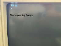
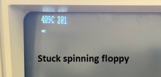
However, it still shows POST errors 409C 201 but proceeds to cassette BASIC when a floppy disk is not inserted. Keyboard works fine etc.

When a floppy disk is inserted it seeks and then either spins the disk forever or stops spinning, but the keyboard in unresponsive (even Ctrl-Alt-Del).

It has two standard DS/DD full height floppy disks. If I disconnect the data cable from the second disk B:, it may occasionally show POST error xx 301 (stuck key), and proceed to boot from disk A: and execute AUTOEXEC.BAT. But they keyboard is unresponsive (even to Ctrl-Alt-Del). Good news is that that both drives seem to be working in such "configuration", i.e. the other is disconnected. The termination resistor array has not effect on the outcome. The 1E shunt switches in both drives are in DS1; and the data cable is twisted on the second connector - a standard IBM configuration.
Also SW1 is set to two floppy drives. It didn't want to boot from floppy with the 1 drive SW1 setting.

(*) I wanted to address the P9 connector (+12v -12v) issue and the POST errors 201 before looking more into the drives.
I am thinking it could be related to the DRAM chips or DRAM refresh circuit.

If this looks familiar or any ideas or pointers how to diagnose these, it would be greatly appreciated.
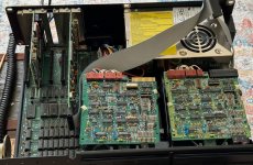
IMG_6530.jpg

IMG_6531.jpg

IMG_6532.jpg
 
P9 should be the -5/+5v side. I’d back up a little and first check the main board for shorts on that 5v side.

On your Rev.B system, -5v is only used for the cassette amplifier circuit and possibly the floppy controller if it’s an early version. The +5v is used by most ISA cards. You should check out Minuszerodegrees.net, a well maintained site with fantastic information.

Also see in your picture the floppy head cables are disconnected?
 
Last edited:
I recently acquired an IBM 5150 Type B (64K-256K), which on first couple of boots showed a POST error PARITY CHECK 2 (maybe with a 201 also).
But then the power supply went dead. I looked around a noticed the fan twitch on power on, so it looked like it going to over-current shut-down mode.
And indeed, when trying different cable unplugging combinations, it was found that diconneting P9 connector (the one with +12v -12v) the power fan started working and computer booted.
I could not find anything specific to the P9 connector or 5150 functioning without it. (*)
Welcome to these forums.

Lots of IBM 5150 information at minuszerodegrees.net

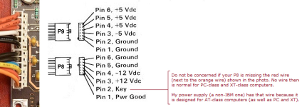
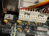
You have your P8 and P9 confused. P8 is the one with +12V and -12V on it. Looking at one of the photos, I am pretty sure that it is P8 that I see disconnected.
That certainly explains why the motherboard powers up. The motherboard is getting +5V via the still connected P9.
Looking at the diagram below, which is removed. P8 or P9 ?

1715306605493.png
 
The termination resistor array has not effect on the outcome.
Although, the second photo is an invalid configuration, because per [here], the one-and-only connected 5.25" drive needs the terminator.

Also see in your picture the floppy head cables are disconnected?
Reference photo at [here]. I am guessing that the number '5' plug is out of sight.
 
However, it still shows POST errors 409C 201 but proceeds to cassette BASIC when a floppy disk is not inserted. Keyboard works fine etc.
A 201 error is a RAM related error.
On your particular computer motherboard type, 5150 64KB-256KB with 10/27/82 BIOS, the "40" portion indicates an error at RAM address 256 KB.
In the photos, 256 KB is the most that you have, a fully RAM populated 64KB-256KB motherboard.
As expected, the POST is failing when it tests non-existent RAM.

Was it a RAM card that you removed from slot #3 ?

If not, it becomes a case of working out why the power-on self test (POST) believes that there is more than 256 KB of RAM in total (motherboard + RAM card/s).
Possibilities will be:
- Incorrect RAM related switch settings on motherboard - not set to 256 KB. There are some switches in block SW1 and some in block SW2. See [here] for the settings on a 64KB-256KB motherboard. Per [here], do not confuse ON with OFF.
- Faulty RAM related switch in SW1 or SW2.
- Switches are good, but not the circuitry that reads the switches.

Regarding the last two. You can get into Cassette BASIC, and so you can use what is shown at [here] to verify that the switches are being read correctly.
 
... it was found that diconneting P9 connector (the one with +12v -12v) the power fan started working and computer booted.
Assuming that this is P8 rather than P9:

P8 supplies +12V, -12V, and the POWER GOOD signal, to the motherboard. Usually, removing P8 from a 64KB-256KB motherboard results in the motherboard not starting, due to the lack of POWER GOOD. But I am aware of some motherboards that will start without POWER GOOD, and your motherboard must be in that category.

There is like a 99.9% probability that the cause is a short-circuit tantalum capacitor on either the +12V line or the -12V line. It is VERY common, as seen at [here]. If this is the cause, the procedure at [here] will lead you to the capacitor (and provide replacement details).
 
1715314287393.png

This is booting to DOS. The following is possibly what is going on:

As explained earlier, the POST/BIOS believes that there is more than 256 KB of RAM present. As a result, so does DOS. When DOS boots, possibly depending on the scenario, DOS may try to use RAM that does not exist, and 'falls over'. This is not an issue for Cassette BASIC, because that only uses the first 64 KB.
 
Thank you @modem7 and @Andrettigto for your responses.
Firstly, sorry for confusion between P8/P9. Yes, it's the 12v P8 that causes the no-power condition, and unplugging P8 makes the power supply spin the fan again (and I did measure voltages when the fan was out, and there were only residual sub 1v on various power rails).

I was just working through the info about the 12v tantalum cap (the C7 in the corner in my case). So it did have a short across it's + and -, so I happily snapped its leg, then realizing it's a three-leg, the second leg. And the result was the same: connecting P8 back caused no-power. And measuring the + and - of where the C7 cap was still showed a dead short (0 ohm).

(I also took out the remaining two cards (the floppy controller and SysDyne! CMG-P), and again P8 was causing no-power.)

So something other than the C7 tantalum cap was shorting the 12v rail. I then followed the referenced
... and also found about the cap on the second 12v rail. So both +12v and -12v have similar tantalum caps.
I measured across the second cap, it was showing a short. So I snapped the second 12v cap. Connected P8 -- and it powered! -- Thank you for creating those Diagnostics pages and sharing them.

So that was one down and two to go. In the following posts I'll address the RAM error and the drives.

5150_12volt_caps_plus_minus_64_256KB.jpg

IMG_6578.jpg
 
A quick clarification about the floppy drives: I tried both with and without the termination and it did not affect the outcome, which is randomly one of the two scenarios:
  • it either did not boot with the RAM 201 error (span forever), or
  • it booted DOS, but with the keyboard error 301, but the keyboard was dead. In this scenario, the speaker also produced coarse long noises instead of the crisp POST beeps.
While testing, it seemed that booting was only reproducible when the other drive's data ribbon was disconnected, so the 5 and 6 connectors on the disconnected drive did not make a difference.
Both of the drives booted eventually, which was a good confirmation to test both the DOS disk and the drives.
And I am hoping when the RAM issues are sorted out, the drive might boot normally.
 
Re: the RAM POST error 201. Yes, the switch RAM setting is wrong, because the removed expansion card was a RAM/Parallel/Serial/RTC card, which was giving POST error 9004 201 and PARITY CHECK 2.
So I removed it to narrow down the diagnostics. And I did not adjust the switch settings.

For the previous configuration with the RAM/etc expansion card and on-board 256K,
- SW1 has 3 and 4 off (correct)
- SW2 had 10110 for positions 1-5, which is 640k total = 384K + 256K on board

For the current configuration without the RAM/etc expansion card and with on-board 256K, it should be
- SW2 having 10011 for positions 1-5, which is 256k total = 0K + 256K on board

RAM_Switches.png

So after adjusting the RAM switch settings, POST has not issues. And it boots to PC-DOS 2.10.

Thank you, @modem7 for the pointers and the excellent analysis of how RAM misconfiguration leads to failed DOS booting.

As for the RAM/Parallel/Serial/RTC card and it's Parity Check 2 error, I'll leave it for later and another thread. I guess the 9004 in 201 will give a clue to what bank to check for faulty RAM chips.

IMG_6579.jpg
 
Last edited:
So that was one down and two to go.
I added the failure to the list at [here]. A page refresh in your browser may be required.

As for the RAM/Parallel/Serial/RTC card and it's Parity Check 2 error, I'll leave it for later and another thread. I guess the 9004 in 201 will give a clue to what bank to check for faulty RAM chips.
Yes. Per [here], 90 means address 576 KB, and the 04 means bit 2.
The card will be configured to start its RAM at motherboard address 256 KB, and so the address in error is at address 320 KB on the card.
The combination of single-bit, and an address after the card's first RAM address, points to a faulty RAM chip, or a RAM chip that just needs to be re-seated in its socket.

And I am hoping when the RAM issues are sorted out, the drive might boot normally.
If you see a 201 error, anything following is compromised.

With only 256 KB fitted, and SW1/SW2 set for 256 KB, it is expected that the 5150 produces no POST errors, and that DOS boots. 256 KB will not be enough for some things that you may want to do post booting.
 
... it booted DOS, but with the keyboard error 301, but the keyboard was dead. In this scenario, the speaker also produced coarse long noises instead of the crisp POST beeps.
One thing common to keyboard and speaker is the 8255 chip (and the 8255 support circuitry).
Per [here], the 8255 is used to read bytes sent by the keyboard. That includes the byte of AAh that the 301 test is expecting the keyboard to send.
Per [here], the 8255 is involved with the production of sound for the speaker.

Let's see if those two intermittent happen-at-the-same-time symptoms continue to show.
 
After setting the RAM switches, it now boots normally. And there are no POST errors.

The POST keyboard error with the coarse long noises is also gone now. I think it was the product of random timing drift when the 12v lines were not present and the wrong RAM switches and resulting other POST errors. It was intermittent, and now completely gone.

So the only problem left is fixing the 384 K RAM Parallel Serial card. -- @modem7 Thank you again for the pointers to the RAM identification.
And I'll try re-seating the RAM chips. Maybe also identifying the faulty chip(s), and re-arranging for a slightly smaller total RAM size.
 
For failures 'down the track':

• Note that the RAM test done by the IBM 5150's POST is crude (due to size and time restrictions), and accordingly, will not detect certain RAM related problems. Therefore, Ruud's Diagnostic ROM (RDR) will be handy to have on hand. Swap out the IBM BIOS ROM for the RDR. RDR's RAM test will detect problems that the IBM 5150's POST does not. It does have specific requirements. More information at [here].

( There is a Supersoft/Landmark Diagnostic ROM available, which appears to partially support EGA, but the diagnostic appears not to detect RAM problems of the addressing type. It is also sometimes misleading, such as the RAM test falsely reporting an error address of 05040. )

• During diagnosis of a RAM related problem, be aware of the 10/27/82 BIOS problem described at [here].
 
Thank you @modem7 for the RAM diagnostic references and the BIOS.

My 5150 came with the IBM Diagnostic floppy disk. I ran it and it all went fine. Of course it probably does not cover the external RAM boards.
And the BIOS option might be more applicable, because when POST fails with PARITY CHECK 2, it doesn't allow going further.
 
My 5150 came with the IBM Diagnostic floppy disk. I ran it and it all went fine. Of course it probably does not cover the external RAM boards.
It will. In the IBM PC family, software cannot interrogate the hardware to work out what conventional memory is where (motherboard or expansion card). The diagnostic just sees a block of conventional memory.

And the BIOS option might be more applicable, because when POST fails with PARITY CHECK 2, it doesn't allow going further.
And if you look at the POST breakdown at [here] any test failure before step 18 results in what appears to be a dead motherboard (no video, no beeps).

If you do not have MDA or CGA capability, note that Ruud's Diagnostic ROM can do partial output to an ASCII serial terminal, or serial software running on a modern computer.

I think that if you you are getting Ruud's Diagnostic ROM, you may as well get the Supersoft/Landmark Diagnostic ROM as well.
 
@modem7 -- Thank you for recommending the diagnostic ROM options.
I should be able to identify and replace the RAM chips using the standard means for now. But it's good to keep in mind.

I moved the discussion about the RAM issues in the 384 Combo board to the thread:
The diagnostic just sees a block of conventional memory.

I was thinking that if you write a few random bytes into a RAM address and then read the same bytes -- it would confirm that this particular RAM address works. And repeating this test of each byte of one RAM block (chip area) after another, you would confirm that it's working.
In the end, ROM is just another piece of code, which could also run from RAM. Though ROM diagnostic would be useful when the first 16K is failing.
And our knowledge of which RAM chips correspond to which RAM addresses would help identify the chip, like we are doing in the new thread for the 384 Combo board.

One caveat, when running Norton Utilities SI (System Information), when it was trying to identify RAM (regardless of BIOS reporting 576K),
it crashed with PARITY CHECK 2.
It seems that this crash is caused by an NMI / watchdog. And a smart RAM check routine in assembler (or even BASIC) would disable the NMI and get away the with the PARITY CHECK crash. But it should identify that write/read values did not match.
Set mask: Write hex 80 to I/O Address hex AO (enable NMI)
Clear mask: Write hex 00 to I/O Address hex AO (disable NMI)
 
I was thinking that if you write a few random bytes into a RAM address and then read the same bytes -- it would confirm that this particular RAM address works. And repeating this test of each byte of one RAM block (chip area) after another, you would confirm that it's working.
DEBUG and Cassette BASIC examples at [here]. However, that will not detect a RAM addressing problem.

One caveat, when running Norton Utilities SI (System Information), when it was trying to identify RAM (regardless of BIOS reporting 576K),
it crashed with PARITY CHECK 2.
SI is assuming that whatever RAM is present is fully functional. (It is sizing, not testing.)

It seems that this crash is caused by an NMI / watchdog. And a smart RAM check routine in assembler (or even BASIC) would disable the NMI and get away the with the PARITY CHECK crash.
Yes, RAM testing software normally disables the NMI. In the DEBUG example at [here], you can see me doing that with "- o a0 0". Same in the Cassette BASIC example.
 
Back
Top