• Please review our updated Terms and Rules here

IBM 5162 Weird CPU reset

Maybe your procedure is correct and we're still after the root cause of the problem. Though, now that I know the boot process a little better, I don't understand why just grounding I/O CH RDY would stop the CPU starting to execute the ROM code on a 5162 since it would still get a ready signal via /SRDY when accessing the ROM (for 0xFE0000-0xFFFFFF, WAIT0 is high) (on a 5170, the /SRDY signal is just tied high).
In the datasheet for the 82284 is:

1685172898760.png

My translation of that (written in a way that I prefer) is:

/READY is LOW when either of the following conditions is true:
Cond #1: [/ARDYEN plus /ARDY are both LOW]
Cond #2 [/SRDYEN plus /SRDY are both LOW]
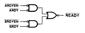
1685173778341.png

Which means that for /READY to be HIGH (what we want for the 'ground I/O CH RDY' procedure), both of the following conditions need to be true:
Cond #1: [/ARDYEN is HIGH] or [/ARDY is HIGH]
Cond #2: [/SRDYEN is HIGH] or [/SRDY is HIGH]

In the 'ground I/O CH RDY' procedure, /ARDYEN and /SRDYEN are LOW. Which means that both /ARDY and /SRDY will need to be HIGH.

It fits with your experiment of, "I tested tying DWAIT0 to ground with a 25ohms resistor (pin 18 on U14) and now the CPU behave has expected on reset with the ground I/O CH RDY procedure." That would have resulted in /SRDY being HIGH.

(As you stated before, on the IBM 5170, the /SRDY pin is tied high via a resistor.)

Does that all sound right ?
 
In the 'ground I/O CH RDY' procedure, /ARDYEN and /SRDYEN are LOW. Which means that both /ARDY and /SRDY will need to be HIGH.
Yes, exactly!
In the 5162, /ARDYEN and /SRDYEN are connected together to the -ARDYEN signal witch comes from a /Q output of a flip-flop, the D input of said flip-flop is tied to the "DATA CONV" signal from U27 (some sort of glue logic chip/rom ?).
I don't know if this is normal, but my -ARDYEN signal was always low when testing, so the CPU would get a low /READY signal as soon as either /ARDY or /SRDY is low (well with different timing sync but that's not relevant here I think)

In the meantime, I recompiled minipro adding a sleep function just before the read of the bipolar PROM and now I get the same file each and every time so this dump should not be corrupted :)
 

Attachments

  • U90.zip
    171 bytes · Views: 1
It fits with your experiment of, "I tested tying DWAIT0 to ground with a 25ohms resistor (pin 18 on U14) and now the CPU behave has expected on reset with the ground I/O CH RDY procedure." That would have resulted in /SRDY being HIGH.

(As you stated before, on the IBM 5170, the /SRDY pin is tied high via a resistor.)

Does that all sound right ?
I completely agree! Now I have to understand why the other 5162 tested with this procedure didn't need the DWAIT0 signal tied to ground to stop executing the BIOS code on boot... :unsure:
 
I completely agree!
I brought out an IBM 5170 motherboard. As expected, grounding the 'I/O CH RDY' line resulted in the 82284's /ARDY pin being taken HIGH.
In the IBM 5170, the 82244's /SRDY pin is tied HIGH via a resistor.
So both /ARDY and /SRDY were HIGH.
As expected, I found the 82244's /READY pin at HIGH.

Experiment: I then grounded the 82244's /SRDY pin, and observed the 82244's /READY pin go LOW.

It certainly points to the requirement that for the 'ground I/O CH RDY' procedure, both /ARDY and /SRDY need to be HIGH.

Now I have to understand why the other 5162 tested with this procedure didn't need the DWAIT0 signal tied to ground to stop executing the BIOS code on boot...
Following are some possibilities that I can think of.

Possibility #1

- The 'ground I/O CH RDY' procedure, as it is written now, works.
- Your U90 ROM is faulty; for motherboard ROM addresses, it should be outputting a LOW to the WAIT0 line. (I.e. Motherboard 'system' ROMs gets a wait state.)

Possibility #2

- Your U90 is good.
- The 'ground I/O CH RDY' procedure, as it is written now, does not work; it should be doing something that results in /SRDY being taken HIGH.
- The person who indicated that the procedure works for them, has a 5162 motherboard that for unknown reason, has the 82244 outputting a HIGH on its /READY pin.

It would be good if another person, who has a known-good 5162 motherboard, try the 'ground I/O CH RDY' procedure for us.
 
Last edited:
Is there someone with an IBM 5162 (I do not have one) who is willing to do a test for us (me and the OP) ?

What we desire is for that person to start the 'ground I/O CH RDY' procedure' at [here], performing steps 1 and 2, and then seeing if the /SRDY pin (pin 2) of the 82284 chip is LOW or HIGH.

Diagram at [here].
 
What we desire is for that person to start the 'ground I/O CH RDY' procedure' at [here], performing steps 1 and 2, and then seeing if the /SRDY pin (pin 2) of the 82284 chip is LOW or HIGH.

Diagram at [here].
/SRDY pin (pin 2) of the 82284 chip is HIGH.
 
Is there someone with an IBM 5162 (I do not have one) who is willing to do a test for us (me and the OP) ?
What we desire is for that person to start the 'ground I/O CH RDY' procedure' at [here], performing steps 1 and 2, and then seeing if the /SRDY pin (pin 2) of the 82284 chip is LOW or HIGH.
/SRDY pin (pin 2) of the 82284 chip is HIGH.
Thank you very much.
 
/SRDY pin (pin 2) of the 82284 chip is HIGH.
Thanks a lot for your help.
Could you also check step 4 of the procedure ? Because my CPU sometimes stops after a few cycle, so if you have address 0xFFFFF0 on the ISA bus like [here] it would mean your CPU stopped on the first instruction (not like mine). :)
 
A12-A31: 00000000000001110000
C2-C8: 0000111

Checked on two working boards.
Not at all like what is expected.

Based on your 5162 thread at [here], you are using a multimeter to determine logic levels. To rule out a measurement issue, please confirm that your LOW's and HIGH's are being determined by the information at [here].

A thought too is that a multimeter may be very inappropriate for the 'ground I/O CH RDY' procedure' . There is an assumption that the initial part of the procedure will result in a 'steady' state, and therefore, a multimeter is okay to use. But what if, for whatever reason, the CPU is not in an endless wait - there is activity. A multimeter will not reveal that, giving misleading results. A logic probe would flash its pulse LED.
 
I tested tying DWAIT0 to ground with a 25ohms resistor (pin 18 on U14) and now the CPU behave has expected on reset with the ground I/O CH RDY procedure.
Even better I can see the correct data on the CPU data lines at this state. ("0x65EA" in my case because I'm using Supersoft BIOS on this test)
The above quote from post #8.

ALOIS54: Per above quote, in the 'ground I/O CH RDY' procedure, the 82284's /SRDY pin is found LOW, but if ALOIS54 does something that results in that pin being found HIGH at power-on time, the expected logic states are measured on the address pins of an ISA slot.

RASK: Two functional motherboards. In the 'ground I/O CH RDY' procedure, the 82284's /SRDY pin is found HIGH, but unexpected logic states are measured on the address pins of an ISA slot.

As I see it, there are two questions:

Q1. In the 'ground I/O CH RDY' procedure, why is the /SRDY pin found LOW for ALOIS54's motherboard, but found HIGH for RASK's motherboards?
- Due to a fault on ALOIS54's motherboard?
- Is it that some 5162 motherboards have different U90 ROM content (e.g. in some U90, motherboard ROM gets zero wait states, and in others, motherboard ROM gets one wait state) ?

Q2. RASK has functional motherboards. In the 'ground I/O CH RDY' procedure, why is RASK not seeing the expected logic states on the address pins of an ISA slot ?
 
I have a theory :
On the 5162 the /ARDY signal is used for RAM cards (0xA0000-0xDFFFF) and for I/O channel (0x100000-0xFDFFFF) and the /SRDY signal is for onboard RAM and ROM.
So grounding the I/O CH RDY signal would only stop the CPU when trying to access addresses associated to the /ARDY signal.
On my board, the CPU is executing a lot of ROM code (I'm using Supersoft BIOS) and resets frequently enough to (almost) always get a /SRDY signal
On RASK's boards, the CPU quickly execute the stock BIOS until it tries to access an address in the /ARDY range and stops at this stage because /ARDY will always stay high with this procedure.

I'm thinking of buying a logic analyzer to continue my troubleshoot, but models with enough bits (ie 32+) aren't cheap! :confused:
 
Just a quick update on my problem : I have finally bought a 32-bit 100Mhz logic analyzer (a Digilent Digital Discovery)
Using this nice instrument I have discovered a first fault : bits 11 and 15 on the data bus (D) were disconnected between the CPU and U100.
After a bit of soldering, now the board starts beeping every single time I'm booting it with the SuperSoft ROM but it still resets/crash after a few seconds... :cry:
So I think I had 2 different problems, a bad connection on the D bus (when the board didn't boot at all) and a corruption/timing/read error problem leading to resets and crashes. I don't think theses 2 problems were related...

I must now find why I have this reset/crash problem, I'm pretty sure this is ROM read errors (because at this stage, the SuperSoft BIOS isn't using any RAM and is just executing ROM code).
I've bough a few Winbond W27E257-12 to help me with this debug, I burned a pair with just a jump to the start of the ROM and completely filled the rest with noop (0x90)
I have to study timings of the 80286 and I might have to buy small probes since this might be a timing problem, I can't simply use the ISA Bus for the address lines... :unsure:
 
Back
Top