• Please review our updated Terms and Rules here

IBM 8573-121/061 10483 POST error

DaehanLee

Member
Joined
Jan 18, 2025
Messages
40
Location
Arizona
Hello everyone,
I am new to this forum. I have joined the forum to get guidance for troubleshooting my ESDI Drives.
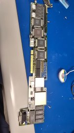
I have three IBM PS/2 P70, one is 8573-121 with Cyrix 486, other two are regular IBM 8573-061.

I originally received those three P70 back in October and began working on restoration in November.
Initially, all system had failed FDD due to leaking capacitor and both 061 had HDD issue. One had few bad sectors with scandisk on DOS 6.22 and other one had physical damage that created sounds of Cessna 172 cranking for engine start.

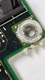
It would have been an easy fix, but I accidentally used wrong capacitance for one of capacitor on FDD. If I remember correctly, I soldered 4.7uF when it is supposed to be 10uF.
So, my -121 suffered from low capacitance and now has short circuit at somewhere. After short, only three diodes illuminates and does not progress to POST.

For my -061, I addressed this issue and used correct capacitor to fix FDD. The result is successful and I have three working FDD for P70. The previous owner had some bad soldering skills and had lots of defect on back panel which caused working FDD head to read but did not spin.
I fixed this issue after my winter break period, and now FDD is both spinning and seeks which leads to IBM Logo reference diskette page.
Initially, 161 and 163 POST will illuminate, which is an easy fix with reference diskette.
After running automatic config, the new error code will show, 10483 which I only had an issue with physically damaged HDD. (Only tested for -061 since -121 is still suffering from short circuit.)

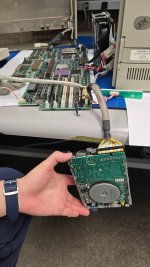
Now I am in a situation where my FDD are working but, all of my ESDI drives are not recognized by mainboards.
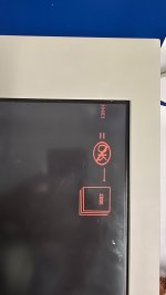
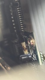
The ESDI drive itself receives power, spins and can hear sounds of seeking. The Diode 15 also illuminate when machine is powered on.
I can clearly hear HDD powering up, spinning and trying to seek. But Front Panel LED does not illuminate HDD diode which should illuminate if HDD is working or seeking during operation.
It seems like after RAM check, the mainboard is trying to boot from HDD, but after a moment, it just spins FDD and boots with my diskette.
1000002952.jpg1000002953.jpg1000002955.jpg1000002905.jpg1000002954.jpg

I have tried to change HDD from 120MB to 60MB and both are not recognized by mainboards anymore. When it was running okay with WIN95, WIN3.11 back in November.

Do you guys have any suggestions? I have never encountered with this error with other PS/2 Machines and ISA computers.
Thank you for looking at my post. Have a great day.
Please let me know if anyone needs more information to make this machine to run like brand new again . . .
 

Attachments

  • 1000002912.jpg
    1000002912.jpg
    754 KB · Views: 2
In addition, when I first boot up with working FDD after resoldering, the disk was placed next to PSU to test functionality. The head is definitely scanning, but did not read anything.
I fixed this issue by displacing away from PSU which creates high EMI and FDD worked very well.

Do you guys think the HDD would have same effect?
 

Attachments

  • 1000002887.jpg
    1000002887.jpg
    1.3 MB · Views: 4
Hello Adrent,
I do not have the tape at this moment. So I placed PSU away from HDD.
1000002965.jpg1000002966.jpg
And HDD data transfer is now working very well. I will ask my professors if they have any EMI shielding tapes so I do not have to spend more just for few feet.

I appreciate for your help to restore my IBM PS/2 P70.

1000002973.jpg

I will try similar method with another 8573 that had same issue once my 100uf 6v caps and 47uf 16v arrives and soldered to HDD PCB.

Thank you,
Daehan
 
Hello Adrent,
1000003338.jpg1000003335.jpg
The EMI shielding tape worked very well and now I am not receiving 10483 POST code.


I have additional question for P70 with newer board.
1000003357.jpg
It seems like the 32.768KHz crystal is dead, do you have any idea which crystals would work for this board??
Unfortunately I can not unscrew three flat screws right now due to extreme corrosion. I would probably have to wait until Monday for tools for removal.

Additonally, this P70 came with 2.88MB Mitsubishi MF356C-799MA drive and I can not Identify what the capacitance and voltage (Maybe 10V?)

1000003364.jpg1000003362.jpg

I appreciate for your help.
Thank you,
 

Attachments

  • 1000003356.jpg
    1000003356.jpg
    885.8 KB · Views: 10
The 8573-P70 is NOT the only one with issues with a failing 32KHz osc. I opened up a P75 to look at the can, and it has brown goo at the top of the can, and at the bottom of the can. Might have been a failure at the top, dribbling down to the end...

Quick research has a normal capacitance of 12.5pF. ESR may vary, one model was 35K ohms.

This failing osc is under the MCA slot / MCA socket bracket, so it is hard as hell to see.

EDIT: Dug up a P70 late planar, it is 8.1mm long x 2.75mm in diameter.

It is marked "P3" and "KSSD9K" "KSS" makes me think of a Japanese manufacturer.

Kinseki
 
Last edited:
Did they use a brown colored adhesive?
The back panel screws are corroded so badly, so I am waiting for additional help from my professors.
1737945830582.webp

I should be able to let you know tomorrow if my school does not close due to winter storm warning.
According to his email, he also think it is corroded and assuming there will be more parts that has corrosion. I can already see some parts of PSU casing is corroded.
Although the keyboard and FDD is in good shape and just need quick recap of the SMD cap on FDC. (It is 2.88MB drive from Mitsubishi) It seems like capacitance value is 33uf. I hope the value is correct, but I assume it is 33uf because first letter is 3 and 10v so it is probably not 39uf caps.

1737946257055.webp

1737946410965.webp
 
The back panel screws are corroded so badly, so I am waiting for additional help from my professors.
View attachment 1293770

I should be able to let you know tomorrow if my school does not close due to winter storm warning.
According to his email, he also think it is corroded and assuming there will be more parts that has corrosion. I can already see some parts of PSU casing is corroded.
The back panel screws are corroded so badly, so I am waiting for additional help from my professors.
This editing thing is wonky.

That case screw is a captive screw that has a light spring under the head. Other than that, there is NO metal under the head. Only the plastic of the case. Sordid makes me think the system was sitting on a damp floor?

I am not concerned with the outer screw head. My kontuzion is inside the case where the screw threads into the HD cage. -IF- only the external screw head is rusted, it should start with slight effort. I used a small screwdriver with a 3mm wide blade to open a P75. If you use a longer width screwdriver, it probably will work. Perhaps a large coin would work as well.

Where the wheels come off the Radio Flyer wagon is -IF- the screw is rusted into the HD cage. I can see NO weg to apply any penetrant to that threaded hole in the HD cage...
Hello,
The professors were able to remove three screws and now I do have an access to entire computer.


Overall, it seems like the previous owner is sponge bob.

20250129_163802.jpg

Luckily, the HDD seems to be in working condition, but almost worn out motor.

83163fd2-ec85-4160-a956-2dd10e95446f.jpg8d64fa52-cad8-4763-903b-e108d4faf14b.jpg bc388fa4-5b2b-46ba-9ca1-c674158f8c67.jpgI have no clue how these happened in the past. Especially those white powder?? Stuff are continuously respawning even after cleaning with IPA multiple times. I have never seen that before.

I attempted to test with my disassembled old planar P70 to see if it is display adapter is not working or the plasma display itself.

Initially, I thought it would be okay to test with old planar since the display adapter has same connector with new one.
However, using the old video adapter killed my working video card and now the plasma display does not work with the video adapter.
5cffe7a5-5c42-4a29-aa26-fe7b667ade83.jpg
I honestly have no idea what parts gone bad while having connection with new main board (A.K.A planar)
Do you have any clue?
I will try to find VGA cable tomorrow to see if I can still get video from CRT VGA Port.
 

Attachments

  • a73c8759-af2c-476b-8bdf-c0fea0f00938.jpg
    a73c8759-af2c-476b-8bdf-c0fea0f00938.jpg
    1 MB · Views: 8
  • 69cfe184-fdc5-4d19-96da-34768325cf89.jpg
    69cfe184-fdc5-4d19-96da-34768325cf89.jpg
    660.2 KB · Views: 5
  • d1bc9830-bc09-4654-a833-3dcc5a53f290.jpg
    d1bc9830-bc09-4654-a833-3dcc5a53f290.jpg
    1.2 MB · Views: 52
index.php


This video card is TOTALLY unknown.

My suspicion is a Japanese adapter.

Three sets of memory, two sets of SOPs and 8x ZIPs. That is not what I expected to see.
79F1359 PG2
79F2496 PV5
79F1358 PD4
79F2497 PC4

That long "VESA" connector is probably for a Font Card...

Looks like oscillators are 2x needed frequency. These are not all XGA or VGA frequencies. I bet some are needed by DBCS...

Y1 50.350 MHz [25.175]
Y2 56.644 MHz [28.322]
Y4 47.424 MHz [23.712]
Y6 58.000 MHz [26.000]
Y? Shiny, can't tell...
 
Last edited:
Are those nicked wires from the Video power cable? They could use some electrical tape, but otherwise look OK. My SWAG is that the PSU was schlamned in and pinched the wires? That or the DBA-ESDI drive, but I don't have a P70 anymore to see the positions.

The corroded solder ring on the PCB might respond to judicious use of scotch-brite or some mildly abrasive pad.

" I attempted to test with my disassembled old planar P70 to see if it is display adapter is not working or the plasma display itself. Initially, I thought it would be okay to test with old planar since the display adapter has same connector with new one. However, using the old video adapter killed my working video card and now the plasma display does not work with the video adapter."

Do you have a refdisk? Can I get all the files, ZIPped, RARed, IMAd, sendt to me? I'm curious about the video card or sysboard ADFs.
 
Last edited:
83X3208 is a RAMDAC

If you can get better shots of the Japanese video card [79F1138], I suggest two slightly overlapping images. Would love to get the P/N for the metal capped chips, so I can compare them to the other Japanese Video cards ...
 
Hello Ardent, here is a better picture of the card.
I think this could be also Korean or Taiwanese card. There is an additional card for the font as you have mentioned. I am unsure which font it is, but it will probably have Kanji/Hanja fonts for this IBM P70 (5545-T0B) The PS/55 was also sold in South Korea so I do see possibility being Korean font or Taiwan.

1000003539.jpg1000003538.jpg
1000003541.jpg
The fuse is blown for this card and I can slightly see something white on the legs of multiple chips.

1000003535.jpg
It seems like this could possibly be a reason why fuse was blown. Do you have any guesses on this board?
Additionally the mainboard only shows power on LED and nothing ever happens. I will let you know about more details for trouble shooting after my calculus class.
Thank you.
 
Are those nicked wires from the Video power cable? They could use some electrical tape, but otherwise look OK. My SWAG is that the PSU was schlamned in and pinched the wires? That or the DBA-ESDI drive, but I don't have a P70 anymore to see the positions.

The corroded solder ring on the PCB might respond to judicious use of scotch-brite or some mildly abrasive pad.

" I attempted to test with my disassembled old planar P70 to see if it is display adapter is not working or the plasma display itself. Initially, I thought it would be okay to test with old planar since the display adapter has same connector with new one. However, using the old video adapter killed my working video card and now the plasma display does not work with the video adapter."

Do you have a refdisk? Can I get all the files, ZIPped, RARed, IMAd, sendt to me? I'm curious about the video card or sysboard ADFs.
Okay, so my professor used microscope to see what those white things are and found out it is oxidized solder, so I am in process of cleaning them.
 
After meditation on the Sponge Bob homicide scene, it sure makes me wonder WHAT all the yellow-orange oxide came from.

I see none of it under the DBA-ESDI cavity. My feeble imagination is sordid at a loss. It seems it was from water over the PSU. Normally, fresh water is a very poor conductor. As long as you let the PSU dry out [as it obviously did], there is no significant danger.

Looking at the PSU case, the lone picture shows a nice shiny outside with no significant rust.

My Spidey-senses are tingling. The DBA-ESDI's PCB is feelthy, you've noticed the recurring white corrosion on the jumper header... What if... this P70 was sitting in water, not up to the system board PCB, but high enough to inundate both the PSU and DBA-ESDI HD ?

I'd look through the grille on the PSU for discoloration of components and/or the PCB [yellow-orange oxide] If you notice any, my SWAG would be to drill out the PSU rivets, open up the PSU, and use Q-tips and something like denatured alcohol and wipe away any deposits.

My pro tip for drilling out the rivet heads, use a pair of vice grips or diagonal cutters or SOMETHING to keep the rivet from spinning as you drill. It really isn't too hard. You just need to drill deep enough so you get the point of the drill level to the bottom of the rivet head. Then you can use a standard screwdriver's blade to get under the remains of the rivet head and pry it off.
 
A thought came to me. If you can use English characters, maybe you can remove the P70 video card and use an XGA or XGA-2 adapter in the long upper slot. Just to finish getting this system running. Are there any video related POST errors when you boot? Wish I could be there, lot easier to troubleshoot...

A thought for the small upside-down slot is a Future Domain MCS-700 / IBM Patriot SCSI-2 controller. Either flavor will do, the FD BIOS boots from ID 0 or 1, the IBM BIOS boots in the celestially blessed ID 6 and downward.
No, I do not get video related post errors, but one long beep and two short beep for 8573-061 which is possibly due to faulty PDPC chip. I am getting a VGA signals out and can see screen with external monitor.

The 5545 is absolutely no post and no beep at all. Only thing visibly bad is that it has corrosions on HDD jumpers, blown fuse F1 from the Adapter and 32Khz RTC oscillator which I showed up above.

I think the original owner used to travel a lot or had business in South Korea and had both windows 3.1 in ENG and 3.1 in KR and the registered as 국민신용은행 which is banking corporate in Korea.
That 8573 with Korean Windows is in good condition and now fixed. The EMI issue was removed as soon as I reassembled with EMI copper tape 3M 1245.

The another 8573 would have been in working condition if I did not plug in 5545 (New Board) to test if display would work.
After this stupid test, I am getting 4.4V on RAMDAC chip and only able to get video from external monitor.

5545 is in worst situation. It does power on and illuminate power on green LED, but it will not do anything. I tried to get CP codes with LPT port and it literally does nothing. No 5V, No LED for codes.
The display adapter has one fuse F1 and that one is already blown when I first check with HP34401A multimeter. I do see oxidized layers on legs, but do not see any continuity.
HDD is luckily in working condition when I tested with another 120MB board and with old planar.
FDD is also spinning and needs capacitor to be replaced.

"Wish I could be there, lot easier to troubleshoot..." I agree, I am still freshmen for EE and concepts required for this 5545 is probably graduate student level lol. I just gotta ask my professors for more help.
 
Back
Top