boohyaka
Member
Hi guys!
First post after years or lurking, the usual introduction")
After many years scouring local ads and such, I was extremely lucky and happy to score a 5160, very rare around here, 10 minutes from my home. My very first home computer in 1987 which started it all when I was 5 years old!
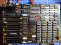
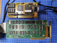
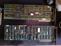
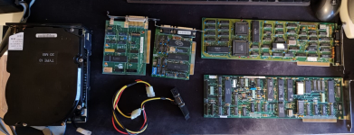
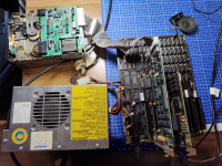
Machine was in a beautiful state, not used for many years, but looking very good. Main unit only, has both an EGA card (yay!) and a VGA Chips card that supports 8-bit, wonderful! No screen or keyboard, I'm not complaining it already felt like striking gold and I should have everything needed at home to at least make sure it work, even if I'd love finding a 5154 and a proper IBM supported keyboard at some point (any hint for those, hit me up :D)
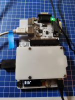
Some deep cleaning, visual inspection, and PSU check later, I'm in basic setup mode to start it up for the first time (FDD controller, beeper, VGA card, keyboard). Starts right up, but "301" error showing up on top. 640kb checked fine so that's nice. I have no "true" XT keyboard so using USB4VC in XT mode. F1 does nothing when prompted after RAM check. Activity comes up on the USB4VC, and numlock + scroll lock do light up the keyboard LED so something is going through. Removed the USB4VC and tried about all my old PS/2 keyboards with a passive PS/2-DIN5 converter, and found at least 2 that seem to support XT as they light up with numlock. But still, 301 on boot and F1 does not work.
Flashed the BIOS to 05/09/86 (just why not), also tried to short pins 2 and 4 in the DIN5 connector to go in maintenance mode, which worked fine, computer booted in basic.
Checked continuity between the 5 pins of the DIN connector to the motherboard, all seems fine.
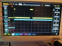
I think that's pretty much it...and thought I'd look for some guidance now as it seems it could be the keyboard controller that is faulty and we're entering the territory where it will all be quite new to me. I should have all hardware necessary, including an oscilloscope that I bought with the hope of teaching myself some electronics but I'm not there yet, and only have surface-level understanding of schematics and how I should test the keyboard circuit, so would need some precise instructions and hand-holding.
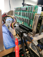
I'm adding some relevant pictures and looking forward to hopefully give a new life to this piece of history!
Cheers and thanks in advance
PS: extra question - case had this DB9 female connector on the small backplate, with a Molex passthrough (male+female)...anybody has a clue what this could used for?
First post after years or lurking, the usual introduction
After many years scouring local ads and such, I was extremely lucky and happy to score a 5160, very rare around here, 10 minutes from my home. My very first home computer in 1987 which started it all when I was 5 years old!
Machine was in a beautiful state, not used for many years, but looking very good. Main unit only, has both an EGA card (yay!) and a VGA Chips card that supports 8-bit, wonderful! No screen or keyboard, I'm not complaining it already felt like striking gold and I should have everything needed at home to at least make sure it work, even if I'd love finding a 5154 and a proper IBM supported keyboard at some point (any hint for those, hit me up :D)
Some deep cleaning, visual inspection, and PSU check later, I'm in basic setup mode to start it up for the first time (FDD controller, beeper, VGA card, keyboard). Starts right up, but "301" error showing up on top. 640kb checked fine so that's nice. I have no "true" XT keyboard so using USB4VC in XT mode. F1 does nothing when prompted after RAM check. Activity comes up on the USB4VC, and numlock + scroll lock do light up the keyboard LED so something is going through. Removed the USB4VC and tried about all my old PS/2 keyboards with a passive PS/2-DIN5 converter, and found at least 2 that seem to support XT as they light up with numlock. But still, 301 on boot and F1 does not work.
Flashed the BIOS to 05/09/86 (just why not), also tried to short pins 2 and 4 in the DIN5 connector to go in maintenance mode, which worked fine, computer booted in basic.
Checked continuity between the 5 pins of the DIN connector to the motherboard, all seems fine.
I think that's pretty much it...and thought I'd look for some guidance now as it seems it could be the keyboard controller that is faulty and we're entering the territory where it will all be quite new to me. I should have all hardware necessary, including an oscilloscope that I bought with the hope of teaching myself some electronics but I'm not there yet, and only have surface-level understanding of schematics and how I should test the keyboard circuit, so would need some precise instructions and hand-holding.
I'm adding some relevant pictures and looking forward to hopefully give a new life to this piece of history!
Cheers and thanks in advance
PS: extra question - case had this DB9 female connector on the small backplate, with a Molex passthrough (male+female)...anybody has a clue what this could used for?
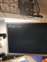

") which is awesome. Here's what I get attached. Same result both without a keyboard connected, and with USB4VC (tried two different PS/2-DIN5 converters).
which is awesome. Here's what I get attached. Same result both without a keyboard connected, and with USB4VC (tried two different PS/2-DIN5 converters).