AK6DN
Veteran Member
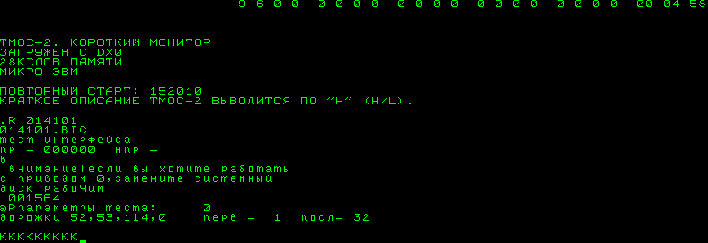
Here is a snapshot of the latest RX02 emulator driver that finally passes the DEC diagnostics. Sometime this week I'll probably upload the entire project to github.
Code:
//
// rx02_driver - Simple :-) RX02 driver
//
// (C) 2013 Don North <ak6dn_at_mindspring_dot_com>
//
// 21 Oct 2013 - donorth - Initial code
// 27 Mar 2016 - donorth - Ported to Arduino from CCS/Microchip
// 23 Sep 2016 - donorth - Added clr_request to end of rx_xmit_es()
// 25 Sep 2016 - donorth - Reworked rx_init_es() to set status function dependent
//
//
// includes
//
#include "my_project.h"
#include "led_driver.h"
#include "rx02_driver.h"
#include "sdcard_driver.h"
//
// definitions
//
// options
#define USE_BIT_BUILTINS 0 // use bit builtins BitRead() etc vs use logical bit shift/mask operations
// RXCS control/status bit definitions
//
// definitions
//
// options
#define USE_BIT_BUILTINS 0 // use bit builtins BitRead() etc vs use logical bit shift/mask operations
// RXCS control/status bit definitions
//efine RXCS_GO (1<<0) // GO bit (reference only; not used in drive)
#define RXCS_FUNCTION (7<<1) // function bitfield
#define RXCS_UNITSEL (1<<4) // unit select
//efine RXCS_DONE (1<<5) // function complete (reference only; not used in drive)
//efine RXCS_INTENB (1<<6) // interrupt enable (reference only; not used in drive)
//efine RXCS_8BIT (1<<6) // 8b mode (RX8E/RX28 ONLY)
//efine RXCS_TR (1<<7) // transfer request (reference only; not used in drive)
//efine RXCS_MAINT (1<<7) // maintenance mode (RX8E/RX28 ONLY)
#define RXCS_DENSEL (1<<8) // density select (RX211/RX28 w/RX02 ONLY)
//efine RXCS_HEADSEL (1<<9) // head select (RX211/RX28 w/RX03 ONLY)
//efine RXCS_NU10 (1<<10) // not used
//efine RXCS_RX02 (1<<11) // RX02 interface (reference only; not used in drive)
//efine RXCS_EXTADDR (3<<12) // upper bits of phys address (reference only; not used in drive)
//efine RXCS_INIT (1<<14) // initialize RX (reference only; not used in drive)
//efine RXCS_ERROR (1<<15) // error flag (reference only; not used in drive)
#define RXFCN_FILL (0) // fill buffer
#define RXFCN_EMPTY (1) // empty buffer
#define RXFCN_WRSECT (2) // write sector
#define RXFCN_RDSECT (3) // read sector
#define RXFCN_SETMEDIA (4) // set media density
#define RXFCN_RDSTAT (5) // read status
#define RXFCN_WRDDSECT (6) // write deleted data sector
#define RXFCN_RDERROR (7) // read error code
// RXES status bit definitions
//efine RXES_CRC (1<<0) // CRC aka READ error
//efine RXES_SIDRDY (1<<1) // side ready (RX211/RX28 ONLY)
//efine RXES_PERR (1<<1) // parity error (RX11/RX8E w/RX01 ONLY)
#define RXES_INIT (1<<2) // controller init done
#define RXES_RX02 (1<<3) // set for RX02 drive (RX28 w/ RX02 ONLY)
//efine RXES_ACLO (1<<3) // set for AC low (RX211 w/RX02 ONLY)
//efine RXES_WPERR (1<<3) // set for write to WP drive (RX11/RX8E w/RX01 ONLY)
#define RXES_DENERR (1<<4) // density error
#define RXES_DRVDEN (1<<5) // diskette double density
#define RXES_DELDATA (1<<6) // deleted data detected
#define RXES_DRVRDY (1<<7) // selected drive ready
#define RXES_UNITSEL (1<<8) // unit selected (RX211 w/RX02 ONLY)
//efine RXES_HEADSEL (1<<9) // head selected (RX211 w/RX03 ONLY
#define RXES_WCOVF (1<<10) // word count overflow (RX211 w/RX02 ONLY)
//efine RXES_NXM (1<<11) // nonexistent memory (RX211 w/RX02 reference only; not used in drive)
// RX error codes
#define RXERR_SUCCESS 0000 // success, no error
//efine RXERR_DR0INIT 0010 // drive 0 failed to init
//efine RXERR_DR1INIT 0020 // drive 1 failed to init
//efine RXERR_STEPHOME 0030 // found home when stepping for init (RX01 ONLY)
#define RXERR_TRKERR 0040 // access to track > 76
#define RXERR_TRKFAIL 0050 // track not found
//efine RXERR_SELFDIAG 0060 // self diagnostic fail (RX01 ONLY)
#define RXERR_SECFAIL 0070 // sector not found
//efine RXERR_WRITEWP 0100 // write to a WP drive (RX01 ONLY)
//efine RXERR_SEPFAIL 0110 // no SEP clock in 40us
//efine RXERR_PREFAIL 0120 // preamble not found
#define RXERR_IDMFAIL 0130 // ID mark not found
//efine RXERR_CRCHEAD 0140 // CRC error on a header (RX01 ONLY)
//efine RXERR_TRKCMP 0150 // header track miscompare
//efine RXERR_IDMTRYS 0160 // too many tries for IDAM
//efine RXERR_DAMFAIL 0170 // data AM not found
//efine RXERR_CRCERR 0200 // CRC error on read
//efine RXERR_PERR 0210 // parity error on word from i/f to controller (RX01 ONLY)
//efine RXERR_RWFAIL 0220 // r/w failed maint test (RX02 ONLY)
#define RXERR_WCOVF 0230 // word count overflow (RX02 ONLY)
#define RXERR_DENERR 0240 // density error (RX02 ONLY)
#define RXERR_KEYERR 0250 // wrong key word for set density (RX02 ONLY)
// macros
// rx interface outputs set/clr
#if USE_BIT_BUILTINS
#define rx_set_done(xxx) bitSet(PORTA,6) /* digitalWrite(PIN_CTLR_DONE_H,HIGH) */
#define rx_clr_done(xxx) bitClear(PORTA,6) /* digitalWrite(PIN_CTLR_DONE_H,LOW) */
#define rx_set_error(xxx) bitSet(PORTA,7) /* digitalWrite(PIN_CTLR_ERROR_H,HIGH) */
#define rx_clr_error(xxx) bitClear(PORTA,7) /* digitalWrite(PIN_CTLR_ERROR_H,LOW) */
#define rx_set_aclo(xxx) bitSet(PORTC,1) /* digitalWrite(PIN_CTLR_ACLO_H,HIGH) */
#define rx_clr_aclo(xxx) bitClear(PORTC,1) /* digitalWrite(PIN_CTLR_ACLO_H,LOW) */
#define rx_set_shift(xxx) bitSet(PORTC,2) /* digitalWrite(PIN_CTLR_SHIFT_H,HIGH) */
#define rx_clr_shift(xxx) bitClear(PORTC,2) /* digitalWrite(PIN_CTLR_SHIFT_H,LOW) */
#define rx_set_out(xxx) bitSet(PORTC,3) /* digitalWrite(PIN_CTLR_OUT_H,HIGH) */
#define rx_clr_out(xxx) bitClear(PORTC,3) /* digitalWrite(PIN_CTLR_OUT_H,LOW) */
#define rx_set_datao(xxx) bitSet(PORTC,5) /* digitalWrite(PIN_CTLR_DATAO_H,HIGH) */
#define rx_clr_datao(xxx) bitClear(PORTC,5) /* digitalWrite(PIN_CTLR_DATAO_H,LOW) */
#define rx_set_request(xxx) bitSet(PORTC,6) /* digitalWrite(PIN_CTLR_TR_RQST_H,HIGH) */
#define rx_clr_request(xxx) bitClear(PORTC,6) /* digitalWrite(PIN_CTLR_TR_RQST_H,LOW) */
// rx interface inputs test
#define rx_tst_pio(xxx) bitRead(PINC,0) /* digitalRead(PIN_CTLR_DMA_MODE_L) */
#define rx_tst_dma(xxx) (rx_tst_pio()?0:1) /* !digitalRead(PIN_CTLR_DMA_MODE_L) */
#define rx_tst_datai(xxx) bitRead(PINC,4) /* digitalRead(PIN_CTLR_DATAI_H) */
#define rx_tst_12b(xxx) bitRead(PINC,7) /* digitalRead(PIN_CTLR_12BIT_H) */
#define rx_tst_8b(xxx) (rx_tst_12b()?0:1) /* !digitalRead(PIN_CTLR_12BIT_H) */
#define rx_tst_run(xxx) bitRead(PINE,4) /* digitalRead(PIN_CTLR_RUN_H)) */
#define rx_tst_init(xxx) bitRead(PINE,5) /* digitalRead(PIN_CTLR_INIT_H) */
#else
#define rx_set_done(xxx) PORTA |= (1<<6) /* digitalWrite(PIN_CTLR_DONE_H,HIGH) */
#define rx_clr_done(xxx) PORTA &= ~(1<<6) /* digitalWrite(PIN_CTLR_DONE_H,LOW) */
#define rx_set_error(xxx) PORTA |= (1<<7) /* digitalWrite(PIN_CTLR_ERROR_H,HIGH) */
#define rx_clr_error(xxx) PORTA &= ~(1<<7) /* digitalWrite(PIN_CTLR_ERROR_H,LOW) */
#define rx_set_aclo(xxx) PORTC |= (1<<1) /* digitalWrite(PIN_CTLR_ACLO_H,HIGH) */
#define rx_clr_aclo(xxx) PORTC &= ~(1<<1) /* digitalWrite(PIN_CTLR_ACLO_H,LOW) */
#define rx_set_shift(xxx) PORTC |= (1<<2) /* digitalWrite(PIN_CTLR_SHIFT_H,HIGH) */
#define rx_clr_shift(xxx) PORTC &= ~(1<<2) /* digitalWrite(PIN_CTLR_SHIFT_H,LOW) */
#define rx_set_out(xxx) PORTC |= (1<<3) /* digitalWrite(PIN_CTLR_OUT_H,HIGH) */
#define rx_clr_out(xxx) PORTC &= ~(1<<3) /* digitalWrite(PIN_CTLR_OUT_H,LOW) */
#define rx_set_datao(xxx) PORTC |= (1<<5) /* digitalWrite(PIN_CTLR_DATAO_H,HIGH) */
#define rx_clr_datao(xxx) PORTC &= ~(1<<5) /* digitalWrite(PIN_CTLR_DATAO_H,LOW) */
#define rx_set_request(xxx) PORTC |= (1<<6) /* digitalWrite(PIN_CTLR_TR_RQST_H,HIGH) */
#define rx_clr_request(xxx) PORTC &= ~(1<<6) /* digitalWrite(PIN_CTLR_TR_RQST_H,LOW) */
// rx interface inputs test
#define rx_tst_pio(xxx) ((PINC & (1<<0)) ? 1 : 0) /* (digitalRead(PIN_CTLR_DMA_MODE_L)==HIGH) */
#define rx_tst_dma(xxx) ((PINC & (1<<0)) ? 0 : 1) /* (digitalRead(PIN_CTLR_DMA_MODE_L)==LOW) */
#define rx_tst_datai(xxx) ((PINC & (1<<4)) ? 1 : 0) /* digitalRead(PIN_CTLR_DATAI_H) */
#define rx_tst_12b(xxx) ((PINC & (1<<7)) ? 1 : 0) /* (digitalRead(PIN_CTLR_12BIT_H)==HIGH) */
#define rx_tst_8b(xxx) ((PINC & (1<<7)) ? 0 : 1) /* (digitalRead(PIN_CTLR_12BIT_H)==LOW) */
#define rx_tst_run(xxx) ((PINE & (1<<4)) ? 1 : 0) /* (digitalRead(PIN_CTLR_RUN_H)==HIGH) */
#define rx_tst_init(xxx) ((PINE & (1<<5)) ? 1 : 0) /* (digitalRead(PIN_CTLR_INIT_H)==HIGH) */
#endif
// INIT/RUN status
#define RX_SAW_NONE 0 // saw neither RUN or INIT
#define RX_SAW_RUN 1 // saw RUN and not INIT
// emulation type
#define RX_TYPE_NONE 0 // no type defined
#define RX_TYPE_RX01 1 // RX02 in RX01 mode
#define RX_TYPE_RX02 2 // RX02 in native mode
#define RX_TYPE_RX03 3 // RX02 in dual-sided RX03 mode (***UNSUPPORTED***)
// drive density
#define RX_DEN_SD 0 // single density mode (128B/sector)
#define RX_DEN_DD 1 // double density mode (256B/sector)
#define RX_DEN_QD 2 // quad density mode (512B/sector) (***UNSUPPORTED***)
// data type
#define RX_DATA_NORMAL 0 // normal data
#define RX_DATA_DELETED 1 // deleted data
// timing characteristics
#define RX_TIME_INIT 0 // initialize floppy drive
#define RX_TIME_SEEK 1 // read/write seek time, position dependent
#define RX_TIME_RDSTAT 2 // read status function
#define RX_TIME_RDERROR 3 // read error registers
#define RX_TIME_SETMEDIA 4 // set media density
// disk definitions
#define RX_NTRKS 77L // number of tracks per disk
#define RX_NSECS 26L // number of sectors per track
#define RX_NBPS 128L // bytes per sector, single density
#define RX_NUNITS 2 // number if units
// convenience macros
#define rx_sec_size(den) (RX_NBPS<<(den)) // bytes per sector at density
#define rx_trk_size(den) (RX_NSECS*rx_sec_size(den)) // bytes per track at density
#define rx_dsk_size(den) (RX_NTRKS*rx_trk_size(den)) // bytes per disk at density
#define rx_get_bits(xxx) (rx_tst_12b() ? 12 : 8) // number of bits signaled by interface
// buffer sizes
#define RX_BUFFER_SIZE (rx_sec_size(RX_DEN_DD)) // maximum size sector buffer for double density
// PRIVATE PRIVATE PRIVATE PRIVATE PRIVATE PRIVATE PRIVATE PRIVATE PRIVATE
// PRIVATE PRIVATE PRIVATE PRIVATE PRIVATE PRIVATE PRIVATE PRIVATE PRIVATE
// PRIVATE PRIVATE PRIVATE PRIVATE PRIVATE PRIVATE PRIVATE PRIVATE PRIVATE
volatile static uint8_t rx_run_seen; // set when RX RUN asserted (rising edge)
volatile static uint8_t rx_init_seen; // set when RX INIT asserted (rising edge)
static jmp_buf rx_init_env; // environment to invoke when INIT is asserted (ie, reset/error condition)
static char fcn_list[][8] = { "FILBUF", "EMPBUF", "WRSECT", "RDSECT", "SETMED", "RDSTAT", "WRDDSE", "RDERRC", "INIT" };
static char den_list[] = { 'S', 'D', 'Q' }; // Single, Double, Quad density flag
static uint8_t rx_type = RX_TYPE_RX02; // default drive emulation, can be overwritten
struct drv_t {
uint32_t dd[RX_NTRKS]; // normal or deleted data per track per sector (1 bit per sector 0..31)
char name[32]; // associated file name
uint8_t rdy; // drive ready
uint8_t den; // density
uint8_t ta; // track address
uint8_t sa; // sector address
uint16_t len; // read/write length
uint32_t pos; // read/write position
};
static struct rx_t {
uint32_t cmdcnt; // count of commands
uint32_t errcnt; // count of errors
uint16_t cs; // control/status image
uint16_t es; // error and status
uint16_t tc; // transfer count
uint8_t wc; // word count
uint8_t ec; // error code
uint8_t unit; // active unit number
uint8_t den; // density selected, SD, DD, QD
uint8_t ta; // track address
uint8_t sa; // sector address
uint8_t type; // emulation type: RX01, RX02
uint8_t timing; // timing mode: 0=fastest, 2=normal/real
uint16_t len; // read/write length
uint32_t pos; // read/write position
struct {
uint8_t code; // function selected (numeric 0..7)
char * name; // function selected, ascii name id
} fcn;
struct drv_t drv[RX_NUNITS]; // drive specific parameters
uint8_t buffer[RX_BUFFER_SIZE]; // sector buffer
} rx;
static HardwareSerial *debugPort = NULL; // debug serial output
static uint8_t debugLevel = 0; // debug level, 0=NONE, higher is more
//
// RX02 INIT assertion interrupt
//
static void rx_intr_init (void)
{
rx_init_seen = 1;
return;
}
//
// RX02 RUN assertion interrupt
//
static void rx_intr_run (void)
{
rx_run_seen = 1;
return;
}
//
// RX time delay routine
//
static void rx_timing (uint8_t type)
{
uint16_t delta;
uint16_t ms_delay;
const uint16_t ms_amount = 5;
// check basic timing mode
if (rx.timing >= 1) {
// otherwise decode timing parameter
switch (type) {
// initialize floppy drive
case RX_TIME_INIT:
ms_delay = 500;
break;
// read status function
case RX_TIME_RDSTAT:
ms_delay = 250;
break;
// read error registers
case RX_TIME_RDERROR:
ms_delay = 10;
break;
// set media density
case RX_TIME_SETMEDIA:
ms_delay = 10000;
break;
// read/write seek time, position dependent
case RX_TIME_SEEK:
// compute track move delta
delta = abs(rx.ta - rx.drv[rx.unit].ta);
// compute seek time based on delta track amount
ms_delay = 20 + ((delta==0) ? 0 : (20 + delta*10));
break;
// none
default:
ms_delay = 0;
break;
}
// for medium timing mode, make delays 1/10 of normal
if (rx.timing == 1) ms_delay = ms_delay/10;
// check for delay requested
if (ms_delay > 0) {
// delay in 5ms increments, checking for INIT
while (ms_delay > ms_amount) {
if (rx_init_seen) { longjmp(rx_init_env, 10); }
delay(ms_amount);
ms_delay -= ms_amount;
}
// final small delay less than 5ms
if (rx_init_seen) { longjmp(rx_init_env, 10); }
delay(ms_delay);
}
}
// all done
if (rx_init_seen) { longjmp(rx_init_env, 10); }
return;
}
//
// wait until the RX_RUN or RX_INIT signal is asserted, or timeout occurs
//
static uint8_t rx_wait_run_or_init (uint32_t expire)
{
uint32_t start = millis();
do {
if (rx_init_seen) { rx_init_seen = 0; longjmp(rx_init_env, 1); }
if (rx_run_seen) { rx_run_seen = 0; return RX_SAW_RUN; }
} while (millis()-start <= expire);
// count timed out with neither RUN or INIT
return RX_SAW_NONE;
}
// wait forever until the RX_RUN or RX_INIT signal is asserted
static uint8_t rx_wait_run_or_init (void)
{
do {
if (rx_init_seen) { rx_init_seen = 0; longjmp(rx_init_env, 2); }
if (rx_run_seen) { rx_run_seen = 0; return RX_SAW_RUN; }
} while (TRUE);
}
//
// receive a 12/8 bit word from the RX interface, msb first
//
#define _rx_recv_hs(xxx,yyy) { if (rx_tst_datai()) { delay_1c(); (xxx) |= (1<<(yyy)); } else { (xxx) &= ~(1<<(yyy)); delay_2c(); } delay_1c(); rx_set_shift(); delay_1c(); rx_clr_shift(); }
static uint16_t rx_recv12_hs (uint8_t handshake)
{
uint16_t data = 0;
rx_clr_out();
rx_clr_done();
rx_clr_datao();
rx_clr_error();
rx_clr_shift();
if (handshake) { rx_set_request(); rx_wait_run_or_init(); rx_clr_request(); }
noInterrupts();
_rx_recv_hs(data,11);
_rx_recv_hs(data,10);
_rx_recv_hs(data,9);
_rx_recv_hs(data,8);
_rx_recv_hs(data,7);
_rx_recv_hs(data,6);
_rx_recv_hs(data,5);
_rx_recv_hs(data,4);
_rx_recv_hs(data,3);
_rx_recv_hs(data,2);
_rx_recv_hs(data,1);
_rx_recv_hs(data,0);
interrupts();
if (rx_init_seen) { longjmp(rx_init_env, 3); }
return data;
}
static uint16_t rx_recv8_hs (uint8_t handshake)
{
uint8_t data = 0;
rx_clr_out();
rx_clr_done();
rx_clr_datao();
rx_clr_error();
rx_clr_shift();
if (handshake) { rx_set_request(); rx_wait_run_or_init(); rx_clr_request(); }
noInterrupts();
_rx_recv_hs(data,7);
_rx_recv_hs(data,6);
_rx_recv_hs(data,5);
_rx_recv_hs(data,4);
_rx_recv_hs(data,3);
_rx_recv_hs(data,2);
_rx_recv_hs(data,1);
_rx_recv_hs(data,0);
interrupts();
if (rx_init_seen) { longjmp(rx_init_env, 4); }
return uint16_t(data);
}
static uint16_t rx_recv (uint8_t n)
{
if (n == 12) return rx_recv12_hs(FALSE); else
if (n == 8) return rx_recv8_hs(FALSE); else
if (rx_tst_12b()) return rx_recv12_hs(FALSE); else
return rx_recv8_hs(FALSE);
}
static uint16_t rx_recv (void)
{
if (rx_tst_12b()) return rx_recv12_hs(FALSE); else
return rx_recv8_hs(FALSE);
}
static uint16_t rx_recv_hs (uint8_t n)
{
if (n == 12) return rx_recv12_hs(TRUE); else
if (n == 8) return rx_recv8_hs(TRUE); else
if (rx_tst_12b()) return rx_recv12_hs(TRUE); else
return rx_recv8_hs(TRUE);
}
static uint16_t rx_recv_hs (void)
{
if (rx_tst_12b()) return rx_recv12_hs(TRUE); else
return rx_recv8_hs(TRUE);
}
//
// transmit a 12/8 bit word to the RX interface, msb first
//
#define _rx_xmit_hs(xxx,yyy) { if ((xxx)&(1<<(yyy))) { delay_1c(); rx_set_datao(); } else { rx_clr_datao(); delay_2c(); } delay_1c(); rx_set_shift(); delay_1c(); rx_clr_shift(); }
static void rx_xmit12_hs (uint16_t value, uint8_t handshake)
{
uint16_t data = value;
noInterrupts();
if (handshake) { rx_clr_request(); }
rx_clr_shift();
rx_set_out();
delay_3c();
_rx_xmit_hs(data,11);
_rx_xmit_hs(data,10);
_rx_xmit_hs(data,9);
_rx_xmit_hs(data,8);
_rx_xmit_hs(data,7);
_rx_xmit_hs(data,6);
_rx_xmit_hs(data,5);
_rx_xmit_hs(data,4);
_rx_xmit_hs(data,3);
_rx_xmit_hs(data,2);
_rx_xmit_hs(data,1);
_rx_xmit_hs(data,0);
delay_3c();
rx_clr_datao();
interrupts();
if (handshake) { rx_set_request(); rx_wait_run_or_init(); rx_clr_request(); }
rx_clr_out();
if (rx_init_seen) { longjmp(rx_init_env, 5); }
return;
}
static void rx_xmit8_hs (uint16_t value, uint8_t handshake)
{
uint8_t data = value;
noInterrupts();
if (handshake) { rx_clr_request(); }
rx_clr_shift();
rx_set_out();
delay_3c();
_rx_xmit_hs(data,7);
_rx_xmit_hs(data,6);
_rx_xmit_hs(data,5);
_rx_xmit_hs(data,4);
_rx_xmit_hs(data,3);
_rx_xmit_hs(data,2);
_rx_xmit_hs(data,1);
_rx_xmit_hs(data,0);
delay_3c();
rx_clr_datao();
interrupts();
if (handshake) { rx_set_request(); rx_wait_run_or_init(); rx_clr_request(); }
rx_clr_out();
if (rx_init_seen) { longjmp(rx_init_env, 6); }
return;
}
static void rx_xmit (uint16_t data, uint8_t n)
{
if (n == 12) rx_xmit12_hs(data,FALSE); else
if (n == 8) rx_xmit8_hs(data,FALSE); else
if (rx_tst_12b()) rx_xmit12_hs(data,FALSE); else
rx_xmit8_hs(data,FALSE);
return;
}
static void rx_xmit (uint16_t data)
{
if (rx_tst_12b()) rx_xmit12_hs(data,FALSE); else
rx_xmit8_hs(data,FALSE);
return;
}
static void rx_xmit_hs (uint16_t data, uint8_t n)
{
if (n == 12) rx_xmit12_hs(data,TRUE); else
if (n == 8) rx_xmit8_hs(data,TRUE); else
if (rx_tst_12b()) rx_xmit12_hs(data,TRUE); else
rx_xmit8_hs(data,TRUE);
return;
}
static void rx_xmit_hs (uint16_t data)
{
if (rx_tst_12b()) rx_xmit12_hs(data,TRUE); else
rx_xmit8_hs(data,TRUE);
return;
}
//
// transmit an extended status word
//
static void rx_xmit_es (void)
{
if (debugLevel) debugPort->printf(F("RX: %s rx_xmit_es(%04o)\n\n"), rx.fcn.name, rx.es);
if (rx_tst_dma() || rx_tst_12b() && rx.type == RX_TYPE_RX02) {
// RX211/RXV21 or RX28 attached
// clear TR, set DONE
rx_clr_request();
rx_set_out();
rx_set_done();
// send the 12b status word
rx_xmit(rx.es, 12);
// pulse TR high
rx_set_request();
rx_clr_request();
} else if (rx_tst_12b()) {
// RX8E attached
// send the 12b status word
rx_xmit(rx.es, 12);
} else {
// RX11/RXV11 attached
// send the 8b status word
rx_xmit(rx.es, 8);
}
return;
}
//
// setup error/status word
//
static void rx_init_es (void)
{
// setup initial value depending upon current function
if (rx.fcn.code == RXFCN_FILL || rx.fcn.code == RXFCN_EMPTY) {
// leave UNIT/DENSITY unchanged
rx.es &= ~(RXES_UNITSEL|RXES_DRVDEN);
} else {
// clear all bits
rx.es = 0;
}
// for certain functions only
if (rx.fcn.code == RXFCN_INIT || rx.fcn.code == RXFCN_RDSTAT) {
// insert drive ready for that unit
if (rx.drv[rx.unit].rdy) rx.es |= RXES_DRVRDY;
}
// certain bits for RX02/RX03
if (rx.type == RX_TYPE_RX02 || rx.type == RX_TYPE_RX03) {
// insert drive type (RX28 only)
if (rx_tst_12b()) rx.es |= RXES_RX02;
if (!(rx.fcn.code == RXFCN_FILL || rx.fcn.code == RXFCN_EMPTY)) {
// insert unit selected (RX211 only)
if (rx.unit == 1 && rx_tst_dma()) rx.es |= RXES_UNITSEL;
// insert density for that unit
if (rx.drv[rx.unit].den == RX_DEN_DD) rx.es |= RXES_DRVDEN;
}
}
// insert init done if in INITIALIZE state
if (rx.fcn.code == RXFCN_INIT) rx.es |= RXES_INIT;
// done
return;
}
// PUBLIC PUBLIC PUBLIC PUBLIC PUBLIC PUBLIC PUBLIC PUBLIC PUBLIC PUBLIC
// PUBLIC PUBLIC PUBLIC PUBLIC PUBLIC PUBLIC PUBLIC PUBLIC PUBLIC PUBLIC
// PUBLIC PUBLIC PUBLIC PUBLIC PUBLIC PUBLIC PUBLIC PUBLIC PUBLIC PUBLIC
//
// initialize the RX subsystem
//
// flag: TRUE for powerup init; FALSE for INIT pulse seen
//
void rx_initialize (uint8_t flag)
{
uint8_t i;
// led status
led_state(red, on);
led_state(green, off);
led_state(yellow, off);
// setup at power up ... required first time only
if (flag) {
// setup pins
pinMode(PIN_CTLR_DMA_MODE_L, INPUT);
pinMode(PIN_CTLR_DATAI_H, INPUT);
pinMode(PIN_CTLR_12BIT_H, INPUT);
pinMode(PIN_CTLR_INIT_H, INPUT); // interrupt capable
pinMode(PIN_CTLR_RUN_H, INPUT); // interrupt capable
//
pinMode(PIN_CTLR_TR_RQST_H, OUTPUT);
pinMode(PIN_CTLR_DATAO_H, OUTPUT);
pinMode(PIN_CTLR_SHIFT_H, OUTPUT);
pinMode(PIN_CTLR_ERROR_H, OUTPUT);
pinMode(PIN_CTLR_ACLO_H, OUTPUT);
pinMode(PIN_CTLR_DONE_H, OUTPUT);
pinMode(PIN_CTLR_OUT_H, OUTPUT);
// setup RX INIT interrupt
rx_init_seen = 0;
attachInterrupt(digitalPinToInterrupt(PIN_CTLR_INIT_H), rx_intr_init, RISING);
// setup RX RUN interrupt
rx_run_seen = 0;
attachInterrupt(digitalPinToInterrupt(PIN_CTLR_RUN_H), rx_intr_run, RISING);
// counters
rx.cmdcnt = 0;
rx.errcnt = 0;
}
// setup control outputs
rx_clr_out();
rx_clr_aclo();
rx_clr_done();
rx_clr_datao();
rx_clr_error();
rx_clr_shift();
rx_clr_request();
// toggle ACLO at initial reset
if (flag) { rx_set_aclo(); delay(100); rx_clr_aclo(); }
// wait for INIT to go away
uint32_t start = millis(); // current time, in ms
uint32_t expire = 10000UL; // 10 sec delay
if (debugLevel) debugPort->printf(F("RX: waiting for INIT to clear ... t=%lums\n"), millis());
while ((rx_init_seen || rx_tst_init()) && millis()-start <= expire) { rx_init_seen = 0; }
if (debugLevel) debugPort->printf(F("RX: INIT has %scleared t=%lums\n"), rx_tst_init() ? "NOT " : "", millis());
// setup drive data structures
rx.type = rx_type;
rx.fcn.code = RXFCN_INIT;
rx.fcn.name = fcn_list[rx.fcn.code];
rx.den = (rx.type == RX_TYPE_RX02 ? RX_DEN_DD : RX_DEN_SD);
rx.cs = 0;
rx.es = 0;
rx.ec = 0;
rx.ta = 0;
rx.sa = 0;
rx.wc = 0;
rx.tc = 0;
rx.len = 0;
rx.pos = 0;
rx.unit = 0;
rx.timing = 0;
// setup drive state
for (i = 0; i < RX_NUNITS; ++i) {
if (flag) sprintf(rx.drv[i].name, "RX%d.DSK", i);
rx_unit_file(i);
}
// clear entire sector buffer
memset(rx.buffer, 0x00, sizeof(rx.buffer));
// indicate SD card access in progress
led_state(yellow, on);
// copy drive 0 boot sector into the buffer, if drive is ready
rx.drv[0].ta = rx.ta = 1;
rx.drv[0].sa = rx.sa = 1;
rx.drv[0].len = rx.len = rx_sec_size(rx.drv[0].den);
rx.drv[0].pos = rx.pos = (rx.ta*RX_NSECS + (rx.sa - 1)) * rx.len;
if (rx.drv[0].rdy) sd_read_bytes(rx.drv[0].name, rx.pos, rx.buffer, rx.len);
// indicate SD card access complete
led_state(yellow, off);
// init time delay
rx_timing(RX_TIME_INIT);
// setup error/status bits and transmit
rx_init_es();
rx_xmit_es();
// led status
led_state(red, off);
return;
}
//
// setup the file for rx drive unit
//
char *rx_unit_file (uint8_t unit, char *name)
{
uint32_t size;
// setup file name if provided
if (name) strcpy(rx.drv[unit].name, name);
// set initial state from common block
rx.drv[unit].ta = rx.ta;
rx.drv[unit].sa = rx.sa;
rx.drv[unit].len = rx.len;
rx.drv[unit].pos = rx.pos;
// zap the deleted data state to normal
memset(rx.drv[unit].dd, RX_DATA_NORMAL, sizeof(rx.drv[unit].dd));
// special file name of "NONE" (any capitalization) maps to an unmounted drive
if (strcasecmp(rx.drv[unit].name, "NONE") == 0) {
// no online disk
rx.drv[unit].rdy = FALSE;
rx.drv[unit].den = RX_DEN_SD;
// return the name
return rx.drv[unit].name;
}
// get size of (existing) file, check it for SD or DD or none; if not SD (RX01,RX02) or DD (RX02) then set it
size = sd_get_file_size(rx.drv[unit].name);
if (rx.type == RX_TYPE_RX01) {
// RX01 only supports SD disks
if (size != rx_dsk_size(RX_DEN_SD))
size = sd_set_file_size(rx.drv[unit].name, rx_dsk_size(RX_DEN_SD));
} else {
// RX02/RX03 supports SD or DD disks, default to DD
if (size != rx_dsk_size(RX_DEN_SD) && size != rx_dsk_size(RX_DEN_DD))
size = sd_set_file_size(rx.drv[unit].name, rx_dsk_size(RX_DEN_DD));
}
// set drive ready if file exists and is a right size (SD or DD)
rx.drv[unit].rdy = (size == rx_dsk_size(RX_DEN_SD)) || (size == rx_dsk_size(RX_DEN_DD));
// set drive density based on file size
rx.drv[unit].den = (size == rx_dsk_size(RX_DEN_DD)) ? RX_DEN_DD : RX_DEN_SD;
// return the name
return rx.drv[unit].name;
}
// setup drive for unit using existing file name
char * rx_unit_file (uint8_t unit)
{
return rx_unit_file(unit, NULL);
}
//
// setup the default emulation type (1=RX01, 2=RX02, etc)
//
uint8_t rx_emulation_type (uint8_t type)
{
rx.type = rx_type = type;
return rx.type;
}
uint8_t rx_emulation_type (void)
{
return rx.type;
}
//
// setup the default timing type (-1=N/C, 0=fastest, 1=medium, 2=slow/normal)
//
uint8_t rx_timing_type (uint8_t type)
{
rx.timing = type;
return rx.timing;
}
uint8_t rx_timing_type (void)
{
return rx.timing;
}
//
// setup the RX02 subsystem debug port
//
uint8_t rx_debug (HardwareSerial *serialPort, uint8_t level)
{
// set debug serial port (or not)
debugPort = serialPort;
// and the debug level
debugLevel = level;
// and done
return debugLevel;
}
uint8_t rx_debug (void)
{
return debugLevel;
}
//
// print RX emulator state
//
void rx_print_state (HardwareSerial *prt)
{
uint8_t i;
// dump to user supplied port if not null
if (prt == NULL) prt = debugPort;
// else try debug port, else return
if (prt == NULL) return;
prt->printf(F("\n\n--- RX Emulator State Dump ---\n\n"));
prt->printf(F(" i/f width = %d.\n"), rx_get_bits());
prt->printf(F(" i/f mode = %s\n"), rx_tst_dma() ? "DMA" : "PIO");
prt->printf(F(" i/f init = %o\n"), rx_tst_init());
prt->printf(F(" i/f run = %o\n"), rx_tst_run());
prt->printf(F("\n"));
prt->printf(F(" rx.cs = %06o\n"), rx.cs);
prt->printf(F(" rx.es = %04o\n"), rx.es);
prt->printf(F(" rx.ec = %04o\n"), rx.ec);
prt->printf(F(" rx.wc = %03o\n"), rx.wc);
prt->printf(F(" rx.tc = %03o\n"), rx.tc);
prt->printf(F(" rx.ta = %03o\n"), rx.ta);
prt->printf(F(" rx.sa = %03o\n"), rx.sa);
prt->printf(F(" rx.pos = %lu.\n"), rx.pos);
prt->printf(F(" rx.len = %u.\n"), rx.len);
prt->printf(F(" rx.den = %c\n"), den_list[rx.den]);
prt->printf(F(" rx.unit = %o\n"), rx.unit);
prt->printf(F(" rx.type = RX0%d\n"), rx.type);
prt->printf(F(" rx.cmdcnt = %u.\n"), rx.cmdcnt);
prt->printf(F(" rx.errcnt = %u.\n"), rx.errcnt);
prt->printf(F(" rx.timing = %o\n"), rx.timing);
prt->printf(F(" rx.fcn.code = %o\n"), rx.fcn.code);
prt->printf(F(" rx.fcn.name = %s\n"), rx.fcn.name);
for (i = 0; i < RX_NUNITS; ++i) {
prt->printf(F("\n"));
prt->printf(F(" rx.drv[%d].name = '%s'\n"), i, rx.drv[i].name);
prt->printf(F(" rx.drv[%d].rdy = %c\n"), i, rx.drv[i].rdy ? 'Y' : 'N');
prt->printf(F(" rx.drv[%d].den = %c\n"), i, den_list[rx.drv[i].den]);
prt->printf(F(" rx.drv[%d].ta = %03o\n"), i, rx.drv[i].ta);
prt->printf(F(" rx.drv[%d].sa = %03o\n"), i, rx.drv[i].sa);
prt->printf(F(" rx.drv[%d].pos = %lu.\n"), i, rx.drv[i].pos);
prt->printf(F(" rx.drv[%d].len = %u.\n"), i, rx.drv[i].len);
}
prt->printf(F("\n"));
return;
}
//
// execute an RX function ... the mainline RX emulator routine, executes one command
//
void rx_function (void)
{
uint16_t i, j;
uint16_t value;
// setup for a new request
rx_clr_request();
rx_clr_out();
rx_set_done();
// setup INIT seen callback
if (setjmp(rx_init_env)) {
// return to here on longjmp(rx_init_env,N);
rx_init_seen = 0;
rx_initialize(false);
return;
}
// wait for RUN or INIT; 25ms timeout if no RUN or INIT
if (rx_wait_run_or_init(25) == RX_SAW_NONE) return;
// RUN seen, process command ...
// receive a command word: 12b on RX211 or RX8E/28 in 12b mode; 8b otherwise
rx.cs = rx_recv(rx_tst_dma() || rx_tst_12b() ? 12 : 8);
if (debugLevel) debugPort->printf(F("RX: cmd=%04o\n"), rx.cs);
// led status
led_state(red, off);
led_state(green, on);
led_state(yellow, off);
// separate out the function field
rx.fcn.code = (rx.cs & RXCS_FUNCTION)>>1;
rx.fcn.name = fcn_list[rx.fcn.code];
// separate out the unit number in the command
rx.unit = (rx.cs & RXCS_UNITSEL) ? 1 : 0;
// separate out the density flag in the command
rx.den = (rx.cs & RXCS_DENSEL) ? RX_DEN_DD : RX_DEN_SD;
// initial error code: success!
rx.ec = RXERR_SUCCESS;
// initial error status
rx_init_es();
// print command
if (debugLevel) debugPort->printf(F("RX: %s unit=%o den=%c\n"), rx.fcn.name, rx.unit, den_list[rx.den]);
// decode command function
switch (rx.fcn.code) {
// === buffer fill or empty ===
//
// DMA: command(12), wordcount(8), N*databytes(8)
// PIO: command(12), N*databytes(8 or 12)
//
case RXFCN_FILL:
case RXFCN_EMPTY:
// compute word count
if (rx_tst_dma()) {
// if DMA mode, receive word count from interface
rx.wc = rx_recv_hs(8);
// receive bus address
// rx.ba = rx_recv_hs(16); // done in RX211 hardware
} else {
// if PIO mode, compute word count from full sector size
rx.wc = rx_sec_size(rx.den) >> (rx_tst_8b() ? 1 : 2);
}
if (debugLevel) debugPort->printf(F("RX: %s wc=%03o\n"), rx.fcn.name, rx.wc);
// transform word count to transfer count
rx.tc = 2*rx.wc;
// check for word count overflow (only can happen on RX211 dma interface with user word count)
if (rx.tc > rx_sec_size(rx.den)) {
if (debugLevel) debugPort->printf(F("RX: %s wc=%03o WCOVF\n"), rx.fcn.name, rx.wc);
rx.ec = RXERR_WCOVF;
rx.es |= RXES_WCOVF;
goto error;
}
// transfer data words in/out
if (rx.fcn.code == RXFCN_EMPTY) {
// empty buffer (RX controller buffer to host interface)
for (i = j = 0; i < rx.tc; ++i) {
if (rx_tst_8b()) {
// extract 8b values from buffer to send as 8b
value = rx.buffer[i];
rx_xmit_hs(value, 8);
} else {
// 12b values are packed into the first 2/3 of the sector; read 2 8b entries and build 12b value
j = 3*i/2;
if (i & 1) {
// odd byte
value = ((rx.buffer[j+0] & 017) << 8) | rx.buffer[j+1];
} else {
// even byte
value = (rx.buffer[j+0] << 4) | ((rx.buffer[j+1] >> 4) & 017);
}
rx_xmit_hs(value, 12);
}
if (debugLevel >= 2) {
if ((i & 7) == 0) debugPort->printf(F("RX: %s %03o:"), rx.fcn.name, i);
if (rx_tst_8b()) debugPort->printf(F(" %03o"), value); else debugPort->printf(F(" %04o"), value);
if ((i & 7) == 7) debugPort->printf(F("\n"));
}
} // for (i = 0; i < rx.tc; ++i)
if (debugLevel >= 2 && (i & 7) != 0) debugPort->printf(F("\n"));
} else {
// fill buffer (host interface to RX controller buffer)
for (i = j = 0; i < rx.tc; ++i) {
if (rx_tst_8b()) {
// 8b values get stuffed into 8b buffer directly
value = rx_recv_hs(8);
rx.buffer[i] = value;
j = i+1;
} else {
// 12b values get split into 4b/8b and merged into two 8b entries
value = rx_recv_hs(12);
j = 3*i/2;
if (i & 1) {
// odd byte
rx.buffer[j++] |= (value >> 8) & 017;
rx.buffer[j++] = value;
} else {
// even byte
rx.buffer[j++] = value >> 4;
rx.buffer[j++] = (value & 017) << 4;
}
}
if (debugLevel >= 2) {
if ((i & 7) == 0) debugPort->printf(F("RX: %s %03o:"), rx.fcn.name, i);
if (rx_tst_8b()) debugPort->printf(F(" %03o"), value); else debugPort->printf(F(" %04o"), value);
if ((i & 7) == 7) debugPort->printf(F("\n"));
}
} // for (i = 0; i < rx.tc; ++i)
if (debugLevel >= 2 && (i & 7) != 0) debugPort->printf(F("\n"));
if (debugLevel >= 2 && j < rx_sec_size(rx.den))
debugPort->printf(F("RX: %s zero fill buffer %03o..%03o\n"), rx.fcn.name, j, rx_sec_size(rx.den)-1);
// zero fill any unwritten bytes at the end of the buffer up to the sector size
while (j < rx_sec_size(rx.den)) rx.buffer[j++] = 0;
}
// indicate transfer is complete
rx.wc = 0;
break;
// === read/write sector ===
//
// command(12), sector(8 or 12), track(8 or 12)
//
case RXFCN_RDSECT:
case RXFCN_WRSECT:
case RXFCN_WRDDSECT:
// first word is sector address (001..032 are valid)
rx.sa = rx_recv_hs() & 0077;
if (debugLevel) debugPort->printf(F("RX: %s sa=%03o\n"), rx.fcn.name, rx.sa);
// second word is track address (000..114 are valid)
rx.ta = rx_recv_hs() & 0377;
if (debugLevel) debugPort->printf(F("RX: %s ta=%03o\n"), rx.fcn.name, rx.ta);
// check drive is ready
if (!rx.drv[rx.unit].rdy) {
// nope, error
goto error;
}
// check track access is valid
if (rx.ta >= RX_NTRKS) {
rx.ec = RXERR_TRKERR;
goto error;
}
// check density matches, error if does not
if (rx.den != rx.drv[rx.unit].den) {
rx.ec = RXERR_DENERR;
rx.es |= RXES_DENERR;
goto error;
}
// check sector address is valid
if (rx.sa < 1 || rx.sa > RX_NSECS) {
rx.ec = RXERR_SECFAIL;
goto error;
}
// compute length of transfer (sector size)
rx.len = rx_sec_size(rx.drv[rx.unit].den);
// compute byte offset into disk image
rx.pos = (rx.ta*RX_NSECS + (rx.sa-1)) * rx.len;
// print details if in debug mode
if (debugLevel) debugPort->printf(F("RX: %s pos=%lu. len=%u.\n"), rx.fcn.name, rx.pos, rx.len);
// bail on INIT seen
if (rx_init_seen) { longjmp(rx_init_env, 20); }
// indicate SD card access in progress
led_state(yellow, on);
// do the read or write
if (rx.fcn.code == RXFCN_RDSECT) {
// do a read; copy data into buffer from diskimage@offset
value = sd_read_bytes(rx.drv[rx.unit].name, rx.pos, rx.buffer, rx.len);
} else {
// do a write
if (rx.fcn.code == RXFCN_WRDDSECT) {
bitWrite(rx.drv[rx.unit].dd[rx.ta], rx.sa, RX_DATA_DELETED);
} else {
bitWrite(rx.drv[rx.unit].dd[rx.ta], rx.sa, RX_DATA_NORMAL);
}
// copy data from rx.buffer[] to diskimage@offset
value = sd_write_bytes(rx.drv[rx.unit].name, rx.pos, rx.buffer, rx.len);
}
// set deleted data status based on sector written or read deldata status
if (bitRead(rx.drv[rx.unit].dd[rx.ta], rx.sa) == RX_DATA_DELETED) rx.es |= RXES_DELDATA;
// SD card access complete
led_state(yellow, off);
// simulate timing
rx_timing(RX_TIME_SEEK);
// update state info for drive
rx.drv[rx.unit].ta = rx.ta;
rx.drv[rx.unit].sa = rx.sa;
rx.drv[rx.unit].pos = rx.pos;
rx.drv[rx.unit].len = rx.len;
// check for read/write error
if (value != rx.len) {
rx.ec = RXERR_IDMFAIL;
goto error;
}
// and done
break;
// === set media density ===
//
// command(12), key(8 or 12)
//
case RXFCN_SETMEDIA:
// this function is a NOP for the RX01
if (rx.type == RX_TYPE_RX01) break;
// first word must be the magic key 'I'
value = rx_recv_hs();
// check key for expected value
if (value != 'I') {
rx.ec = RXERR_KEYERR;
goto error;
}
// check drive is ready
if (!rx.drv[rx.unit].rdy) {
// nope, error
goto error;
}
// simulate timing
rx_timing(RX_TIME_SETMEDIA);
// bail on INIT seen
if (rx_init_seen) { longjmp(rx_init_env, 21); }
// indicate SD card access in progress
led_state(yellow, on);
// change density to requested value AND always zero the entire disk image
sd_set_file_size(rx.drv[rx.unit].name, rx_dsk_size(rx.den));
// update disk parameters to match new size
rx_unit_file(rx.unit);
// update status since may have changed unit density
rx_init_es();
// indicate SD card access complete
led_state(yellow, off);
// and done
break;
// === read status ===
//
// command(12)
//
case RXFCN_RDSTAT:
// simulate timing
rx_timing(RX_TIME_RDSTAT);
// and done
break;
// === read error code ===
//
// command(12)
//
case RXFCN_RDERROR:
if (rx_tst_dma()) {
// RX211/RXV21; return four 16b status words
// simulate timing
rx_timing(RX_TIME_RDERROR);
// receive bus address
// rx.ba = rx_recv_hs(16); // done in RX211 hardware
// generate status byte
value = (rx.unit == 1 ? (1<<7) : 0)
| (rx.drv[1].den == RX_DEN_DD ? (1<<6) : 0)
| (rx.drv[rx.unit].rdy ? (1<<5) : 0)
| (rx.drv[0].den == RX_DEN_DD ? (1<<4) : 0)
| (rx.den == RX_DEN_DD ? (1<<0) : 0);
// print error block
if (debugLevel >= 2) {
debugPort->printf(F("RX: %s Word%d: %03o %03o\n"), rx.fcn.name, 1, rx.wc, rx.ec);
debugPort->printf(F("RX: %s Word%d: %03o %03o\n"), rx.fcn.name, 2, rx.drv[1].ta, rx.drv[0].ta);
debugPort->printf(F("RX: %s Word%d: %03o %03o\n"), rx.fcn.name, 3, rx.sa, rx.ta);
debugPort->printf(F("RX: %s Word%d: %03o %03o\n"), rx.fcn.name, 4, rx.drv[rx.unit].ta, value);
}
// word 1
rx_xmit_hs(rx.ec, 8);
rx_xmit_hs(rx.wc, 8);
// word 2
rx_xmit_hs(rx.drv[0].ta, 8);
rx_xmit_hs(rx.drv[1].ta, 8);
// word 3
rx_xmit_hs(rx.ta, 8);
rx_xmit_hs(rx.sa, 8);
// word 4
rx_xmit_hs(value, 8);
rx_xmit_hs(rx.drv[rx.unit].ta, 8);
} else if (rx.type == RX_TYPE_RX01) {
// RX11/RXV11/RX8E; return EC register in DB
// return EC instead of ES
rx.es = rx.ec;
}
// and done
break;
} // switch (rx.fcn.num)
done:
rx.cmdcnt++;
rx_xmit_es();
led_state(green, off);
return;
error:
rx.errcnt++;
rx_set_error();
led_state(red, on);
goto done;
}
// the end
Last edited:


") I guess.
I guess.