• Please review our updated Terms and Rules here

KayPro 10 Intermittent Issues with Booting

QuillOmega0

Member
Joined
Aug 8, 2022
Messages
26
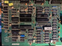
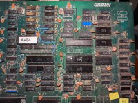
So I got my Kaypro 10 hauled out to finally start refurbishing it. I replaced the RIFA caps and found the voltages are good. System powered up but MFM drive tested bad. I replaced it with an MFM Emulator successfully.
I reloaded the system from the reload disks to the emulator which was flawless.
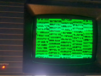
However after some time with the system I started noticing odd behavior. The line borders in MASMENU were starting to break or not be drawn at all. The computer also started locking up randomly, regardless of temperature.
Randomly the machine would lockup on either a cold or a warm boot with the flashing cursor at the top left and with the floppy disk drive light solid. Other times it displayed the ROM version and refused to proceed or continued to boot off the floppy and then froze or took unusually long.

I'm at a puzzlement to figure out where to go from here and what I should be looking at to narrow down the cause.
 
Maybe the first place to point fingers is at memory. Do you have a way to test the DRAM chips? or do you have any replacements to try? If the 5V is "marginal" anywhere on the mainboard, that might indicate the problem. More unlikely causes, powerline glitches, flakey disk transfers, bad originals that you loaded the HDD from.
 
When it locks up I'd check the +5.0 VDC at the CPU, then check all the CPU Control Signals
that are INPUTS to the CPU to make sure they are all HIGH, and not causing the problem:

Pin 16 /INT
Pin 17 /NMI
Pin 24 /WAIT
Pin 26 /RESET

Next, I'd use the back of my Index Finger to see if any of the RAM CHIP's are HOT. If they
are internally shorted they can get VERY HOT. You might also want to check the Video RAM
IC's while you are doing that.

If that all checks good I'd make a NOP tester from a SPARE Z80 CPU, by bending all the DATA
Pins put so they do not go into the Motherboard IC Socket, and jumper a piece of wire wrap wire
from D0 thru D7, and then terminate it on the GND pin of the CPU. That will you to look at each
Adddress Line with an O'scope looking for problems with them throughout the Motherboard.

That will allow you to check the address lines on the motherboard.

Next step would be to build the Z80EXER and use it to have a look at RAM, Video RAM, and to
modify blocks of RAM with DATA to make sure it retains the proper data and bits aren't stuck
High or Low.


Larry
 
Next step would be to build the Z80EXER and use it to have a look at RAM, Video RAM, and to
Or try an MCLZ8 which can also exercise the motherboard via the Z80 socket.
I just used it to locate a faulty DRAM on an Osborne 1: Osborne 1 Debug
 
When it locks up I'd check the +5.0 VDC at the CPU, then check all the CPU Control Signals
that are INPUTS to the CPU to make sure they are all HIGH, and not causing the problem:

Pin 16 /INT
Pin 17 /NMI
Pin 24 /WAIT
Pin 26 /RESET

Next, I'd use the back of my Index Finger to see if any of the RAM CHIP's are HOT. If they
are internally shorted they can get VERY HOT. You might also want to check the Video RAM
IC's while you are doing that.

If that all checks good I'd make a NOP tester from a SPARE Z80 CPU, by bending all the DATA
Pins put so they do not go into the Motherboard IC Socket, and jumper a piece of wire wrap wire
from D0 thru D7, and then terminate it on the GND pin of the CPU. That will you to look at each
Adddress Line with an O'scope looking for problems with them throughout the Motherboard.

That will allow you to check the address lines on the motherboard.

Next step would be to build the Z80EXER and use it to have a look at RAM, Video RAM, and to
modify blocks of RAM with DATA to make sure it retains the proper data and bits aren't stuck
High or Low.


Larry
Thanks Larry, Voltage is fine to the CPU, all board voltages look fine.

I checked all 4 pins, they are all high.
What is interesting if I do get the machine to boot and it crashes. I issue a reset, I confirm pin 26 goes low, but when the system comes back up, no code is executed and everything that was on the screen remains on the screen (junk or text) so I believe monitor ROM isn't being executed. The cpu does get fairly warm but not too hot to touch.
 
Could there be something "flaky" about the system control port - which includes the bit used to turn the ROM on/off (or something in that signal path to the ROM)? Since the Kaypro BIOS routinely switches back and forth between ROM and BIOS (in high RAM), that could certainly cause a crash if it did not work correctly. RESET is supposed to force that bit "on" to enable ROM, but perhaps even that is failing which would result in no initialization, leaving "garbage" or the previous screen contents in the video RAM.
 
Could there be something "flaky" about the system control port - which includes the bit used to turn the ROM on/off (or something in that signal path to the ROM)? Since the Kaypro BIOS routinely switches back and forth between ROM and BIOS (in high RAM), that could certainly cause a crash if it did not work correctly. RESET is supposed to force that bit "on" to enable ROM, but perhaps even that is failing which would result in no initialization, leaving "garbage" or the previous screen contents in the video RAM.
I wouldn't know how to diagnose the system control port. Is this controlled by the SIO? Would I be able to swap the Kaypro's SIO's around to see if I get a different result?
 
Depending on the version of K10 you have (mainboard model), the specific chip(s) involved would move around. The system control port is implemented in descrete components as of Kaypro 10 and the '84 models. Basically, it is a 74LS373 latch, and then some logic gates that take the "bank" bit over to the ROM. I guess there is also the logic which selects the latch itself (the IORQ logic) which *might* be at fault. If you connect a probe (ideally oscilloscope) to the ROM /CE pin, and can get into the state where a RESET does not clear things, you could see whether the /CE signal is ever active. The /CE signal is not a steady state, so it might be easier to hunt down the latch and put a probe on the BANK signal.

If you have the cover off, snap a photo of the mainboard and post.
 
Sure, Here's my board. Don't mind the CPU/ROM modification, I've tested the system without those mods installed and results were the same.
 

Attachments

  • KP-Board.jpg
    KP-Board.jpg
    1.7 MB · Views: 14
Here's the enable pin on the PROM while it's frozen.

It does seem to be thermally related as the problem doesn't occur on a cold boot when it's had a while to cool off. But it happens shortly after
 

Attachments

  • vlcsnap-2022-08-09-10h20m45s424.png
    vlcsnap-2022-08-09-10h20m45s424.png
    804.8 KB · Views: 12
  • SDS00001.jpg
    SDS00001.jpg
    65.2 KB · Views: 12
QuillOmega0,
Your vlcsnap-2022-08-09-10h20m45s424.png file was upside down, so I rotated it 180 Degrees.
In looking at the first two lines there is a repeating pattern that appears to happen 5 times in
the 80 Column width. There are 80 Columns in width for the Kaypro. 80 divided by 5 is 16.
16 = 2^4th power. So, RA4 (Video Address Line A4) for the Video Display is causing the problem
you are seeing. Notice that Reverse Video is also enabled.

I haven't located a schematic for the Kayro 10 that doesn't have the 40 Pin Custom Gate array
81-189. I don't see U10 on your Motherboard's png file.

Larry
 
QuillOmega0,
Sorry, I won't have much time to devote to this issue this week. The signal on /PROMCE looks reasonable, so I'm guessing that there is no issue with the BANK handling. That video pattern: is that after pressing RESET? or after a power-on? I thought a power-cycle always cleared the issue... Do you always get a pattern like that, or is it sometimes something else (like the prior contents of the screen)? The pattern may be nothing more that the natural power-on garbage in static RAMs, although it does look a lot like typical DRAM power-on, which could indicate that it is being copied into video RAM from DRAM.

The Kaypro technical manual http://www.bitsavers.org/pdf/kaypro/1484-F_Kaypro_Technical_Manual_Sep85.pdf contains the schematics for your version of the Kaypro-10 mainboard, starting on physical page 51. This mainboard does not include the custom-LSI chip to do the video, so that makes it easier to fix - *IF* there is anything wrong with the video (I'm not convinced there is evidence).
 
Here is the information around U60 for UNDERLINE, BLINKING, HALF INTENSE, and INVERSE Video.


Four Video Modes of Kaypro 10

74LS373 U60
Code:
D7A            Input    Pin 3    Output        U60 Pin 2    E1
D6A            Input    Pin 18    Output        U60 Pin 19    E2
D5A            Input    Pin 4    Output        U60 Pin 5    E3
D4A            Input    Pin 14    Output        U60 Pin 15    E4
D3A    UNDL    Input    Pin 8    Output        U60 Pin 9    Underline
D2A    BLNK    Input    Pin 13    Output        U60 Pin 12    Blinking
D1A    HLF    Input    Pin 7    Output        U60 Pin 6    Half Intense
D0A    INV    Input    Pin 17    Output        U60 Pin 16    Inverse

Larry
 

Attachments

  • Kaypro10-modes.txt
    403 bytes · Views: 2
I went ahead and attached far better pictures of the mainboard and cleared up the obscurity of U10 as that is hidden a bit.

In regards to the issue to reproduce:
1. If the machine has been off for a while and has cooled down. The system boots normally without issues to the monitor ROM.
2. After a while the machine will lock up / freeze. No video glitches or artifacts appear.
3. Hitting reset at this point causes the display to disappear while the reset button is held down, When the reset button is released, the video display comes back to exactly what was on the screen before.
4. Powering off the machine and powering it back on displays the garbled pattern posted earlier.
5. Letting the machine cool off for a while and then powering it back on, it boots fine again.
 

Attachments

  • PXL_20220810_151417192.jpg
    PXL_20220810_151417192.jpg
    4 MB · Views: 3
  • PXL_20220810_151452274.jpg
    PXL_20220810_151452274.jpg
    3.7 MB · Views: 3
I pulled the cpu and checked pin 34 which is the A4 address line and that does look active But hard for me to tell

Voltages on pins 40-30 are as follows without the CPU:
A10 - 40: .7V
A9 - 39: .7V
A8 - 38: .7V
A7 - 37: 1.5V
A6 - 36: 1.5V
A5 - 35: 1.5V
A4 - 34: 2V
A3 - 33: 2V
A2 - 32: 2V
A1 - 31: 1.5V
A0 - 30: 1.5V
 

Attachments

  • SDS00002.jpg
    SDS00002.jpg
    59.7 KB · Views: 2
Last edited:
QuillOmeag0,
If you look at the vlc*.png of the display there are a few characters such as p and the Plus/Minus
that are correct. There are also 25 rows of characters and graphics.

It appears to me the graphic characters are caused by some the most significant 4 bits being set,
causing Graphic Characters. So, in the case of Plus/Minux Character at 0x07 a character such as
the graphic at 0x87, 0x97, 0xA7, 0xB7, 0xC7, 0xD7, 0xE7, or 0xF7 is being displayed.

I've attached the decoded Character Generator as a Text file.

Larry
 

Attachments

  • 81-187.txt
    118.5 KB · Views: 4
Thanks Larry, If I pull U36, will that allow the CPU to execute code from the ROM? Even if the display is blank?

Anyway now I'm not getting any display at all on boot so I need to go through from scratch.

At this point I may just say screw it and get a new board and give this board to someone with the skills better then I have
 
I fear you may be chasing ghosts by looking in the video area. I suspect the problem is with main CPU/computer hardware. But, one thing to note is that the "A4" that is affecting video refresh has nothing to do with the CPU A4. The CPU does not refresh the video, that is done by the CRTC 6545 which has it's own, separate, address bus. Again, I don't believe your problem has anything to do with A4 being faulty, no matter what the source.
 
I agree, I found my non display was due to an issue with the CPU socket, I fixed it and confirmed it's back to the old symptoms.

I've replaced the Z80 as well with no change.
 
Back
Top