• Please review our updated Terms and Rules here

Kaypro 2/84 Troubleshooting

ngtwolf

Veteran Member
Joined
Apr 6, 2018
Messages
991
Location
Los Angeles, CA
Hi All,

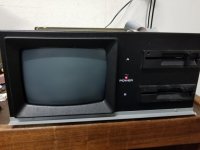
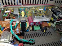
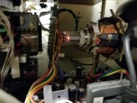
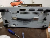
Last weekend I was given a Kaypro 2/84 that didn't work, since the previous owner (also a retro collector) didn't want to mess with troubleshooting or the space it took. Got it home, cleaned it up and started troubleshooting. There were a few physical issues like a broken keyboard connector that i've gotten working temporarily (I think, but I guess we'll see). Initially turning the machine on/off, the power would randomly come on. When it did come on, the power light would come on and the disk drives would spin. There was no display on the screen (if I look closely I can see some light, but very little.. adjusting both the brightness and internal subbrightness made no difference there - the CRT does light up though). I cleaned the machine, resocketed everything and used deoxit on the sockets and power plug. That seemed to solve the random power issues (at least for now). Checking the voltages on the board gave me +12, -12 and +5 voltages. Further troubleshooting noted that the Z80-1 cpu and one of the SIO chips got extremely hot. I swapped the Z80 with my Model 4 and it was indeed bad. I Swapped both of those chips for 'new' chips. As well, it seems the SY6545-1 gets fairly hot, but swapping that made no difference and I assume that's just a hot chip in general. All of the chips now are under 45C with the only ones getting warm being that SY6545 and the Z80 CPU, but still around 45C or less in the hottest area. I tested all the voltages on the board, they all get about 4.9v (except two 12v chips) with the Z80 CPU getting around 4.7V. The ROM in the machine is correct with the 81-292A version (loaded and compared with my eprom burner, at least the first page). It does have a different character rom then is normal for that machine, don't think that matters however at this point. I used IMD to create a 2.2G SSDD disk, but inserting the disk does nothing and it doesn't attempt to read. The floppy drives, while constantly spinning, don't ever turn on the lights (I did clean and oil the drives in the initial cleaning process, as an aside, and physically they look good). The voltage on the drives appear correct as well.

So, at this point I think i've exhausted basic troubleshooting and looking towards some ideas of what my next steps would be? I do have a scope though my skills with it are pretty limited, so it's usually not my first approach. :)
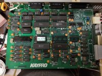
20181011_230859.jpg20181011_230914.jpg20181008_152059.jpg20181007_191933.jpg20181007_215705.jpg20181011_012110.jpg

Thanks!
 
My first concern is Vcc at the CPU. 4.7V seems low, that is outside the 5V+/-5% specification. You might need to track down where/why you are getting that voltage drop. With the 81-292a ROM, you should be seeing this in the middle of your screen (and Drive A LED should be ON):

Code:
                               *     KAYPRO      *


                     Please place your diskette into Drive A

I cannot read your diskette.

So if the screen is blank, some hardware is still not working correctly (could be video, but also could be CPU, etc).

I also see that the label on the ROM is hand-written, so it is probably not original Kaypro issue - but I assume it is a faithful copy. The label also says "CPM 2.1g" which must be a mistake, as I believe Kaypro only used CP/M 2.2.

Hah! So the rom was missing the label altogether, i put a new label over it to cover the Eprom part and wrote that on there after I confirmed the rom with eprom programmer. It should say 2.2g, I just didn't write that well, I guess.

Also noted about what I should be seeing, but it definitely isn't getting far enough into the process to even display anything on the screen. Didn't seem like a CRT issue (at least not at this point) since it doesn't begin to even attempt to try and boot a disk. In any case, any idea where I should be looking for this voltage drop? You're likely onto something because I also noted that the CPU i pulled from the working TRS-80 is actually getting a lower voltage (around 4.1), but it works fine in the Model 4.
 
Being a Kaypro Guy. My play would be to do a 1+1=1... Try to round up another K with an 84 Mainboard. Starting with a working PS and Monitor helps.

I'm a component level swapper, I don't have a shop bench and scopes like I did years ago. I was patient and I ended up building a killer K10 with al SSD Floppy and HD. Also replaced the Case fan... virtually silent, and 56MB of storage.

JA
 
I don't have a lot of experience resurrecting old machines, but my guess would be either damaged traces or shorted capacitors - probably tantalum but possibly electrolytics (ceramics bypass caps are not likely to go bad - unless physically damaged).

If you don't have it already, maybe download the technical manual from http://www.bitsavers.org/pdf/kaypro/1484-F_Kaypro_Technical_Manual_Sep85.pdf and start working from the power supply to the CPU (it has schematics as well as PCB layout). You could also start measuring Vcc at all the chips and perhaps see a brown-out pattern that might lead to the culprit. I guess also measuring voltage across the caps, too. If the Vcc at the power supply connector is good, seems like there has to be something on board that is dropping the voltage. Clearly, Vcc is pretty low at the CPU. I suppose it could even be something like a bad solder joint at the socket. Sometimes, bad solder joints defy visual inspection. With a sensitive volt meter you should be able to measure for voltage drop between key points, like Vcc near the CPU and the actual pin on the CPU. Also, ground could be the fault as well. You could try measuring Vcc on various chips but keep the ground at the CPU (etc). Different combinations of such.
 
Really nice machine!

Some more basic troubleshooting; but you'll need a logic probe (a cheap chinese unit works fine enough) to achieve this. Of course, if you have an expensive oscilloscope works also great!

With this probe you can check the Z80, the Z80 reset sequence and stuck address lines, if your multimeter has a frequency meter, you can check that the CPU clock is being received.
More ideas, I don't really know the 6545 CRTC; but it outputs VSync & HSync through pins 40 and 39 so using the above frequency meter you can check that it outputs the usual 15Khz (HSync) and, I guess, 60Hz VSync. I think that they're (TTL) NTSC compatible signals; but beware that I'm not 100% confident about this...
Also, the 6545 seems that outputs an active high signal when it's generating a display, the pin is named "DISPLAY ENABLE", you can also try to check if it reports that it's working. The Kaypro generates a video signal that is being fed to the internal monitor, I've not checked the schematics to locate this signal; but using the sync signals and the video one you can, adapting TTL voltages, interface an external composite monitor.

Btw, I suposse you already have the schematics.
 
Btw, I suposse you already have the schematics.

Yup, I have those and an oscilloscope. I've tracked it down to there being no signal on the 16mhz crystal. However, I don't think it's that (I'll confirm by swapping that out - i have none on hand, but it seems unlikely it's bad), but rather the '81-194' chip. I've check pins 38 and 39 and they're both getting about 1.2v coming out on those pins (vs 5v on pin 36). Maybe someone with a working system can confirm what those voltages are supposed to be coming out of that chip. If it is a bad chip, which i'm thinking it might be (there was also a bad z80 chip on there as well, and a bad SIO chip (confirmed by testing the z80 chip in my trs-80 and the sio chip was just hot as heck no matter which of the two sockets i swapped it between)), I'm guessing that's basically an ir-replaceable chip, eh?
 
I'm not sure how you're measuring voltage on those pins - are you using the oscilloscope or a voltmeter? Those are signal pins, so measuring with a voltmeter isn't really going to tell you anything. If a voltmeter measures 5v on pin 36 (4MHz), though, that may suggest there is no clock to the CPU.
 
I'm not sure how you're measuring voltage on those pins - are you using the oscilloscope or a voltmeter? Those are signal pins, so measuring with a voltmeter isn't really going to tell you anything. If a voltmeter measures 5v on pin 36 (4MHz), though, that may suggest there is no clock to the CPU.

I've used both. I used the Scope originally, that's how I determined that there was no 4mhz clock signal on the board, which I traced back to the 16mhz Quarts Crystal as doing nothing. Here's where I wasn't sure, however. The 16mhz quartz crystal connects directly to pins 38 and 39 on the Kaypro chip. There is no mention anywhere of what is supposed to be feeding out of those two pins, so I can't tell if the Quartz crystal isn't working because the Crystal is bad, or if it isn't working because the voltage being fed to it from the kaypro chip is low (seemed like the 1.x volts from those pins were low, but there is no way to be sure without having another kaypro to compare to as it's not listed in the manual and it's a custom chip so can't look up a datasheet).

In any case, I'm going to swap out the Crystal so I'll know soon if that was bad or not, but it may also be just one of the many issues on the board (like the bad z80 and sio chips). My only concern really is that if it's that chip that's bad, I'm likely screwed. Most of the other chips I can swap out easily enough, but that one isn't a replaceable part as far as I can tell.
 
The 81-194 is a custom LSI chip, as I recall. I've not seen any specs or datasheet for it. Those inputs (38,39) are probably analog, and so you might not see +5V in any form there. Also, it's possible for a probe to disrupt the crystal and cause it to stop oscillating, although if you don't see 4MHz on pin 36 (with nothing touching pins 38, 39) that's a pretty good sign that the crystal, or oscillator circuitry, is not working. Again, look for signals on those pins, not DC voltage. You should see a decent square-wave 4MHz signal on pin 36 if all is well, ranging from near-0V to near-5V. It's also conceivable that some component like the capacitors have gone bad, but that's less likely. I think it's just a "standard" 16MHz crystal, those are still available right?
 
The 81-194 is a custom LSI chip, as I recall. I've not seen any specs or datasheet for it. Those inputs (38,39) are probably analog, and so you might not see +5V in any form there. Also, it's possible for a probe to disrupt the crystal and cause it to stop oscillating, although if you don't see 4MHz on pin 36 (with nothing touching pins 38, 39) that's a pretty good sign that the crystal, or oscillator circuitry, is not working. Again, look for signals on those pins, not DC voltage. You should see a decent square-wave 4MHz signal on pin 36 if all is well, ranging from near-0V to near-5V. It's also conceivable that some component like the capacitors have gone bad, but that's less likely. I think it's just a "standard" 16MHz crystal, those are still available right?

I did test the other crystals on there with the scope, the 5mhz and the 18mhz, and both of those were presenting a sinewave signal (so i know what i should be seeing and that my scope was set properly), it was just the 16mhz that wasn't doing anything. Yup, I just need to pick up a 16mhz crystal, I just don't have any. I'll get one this weekend.

And yeah, that's what I'm hoping about the 81-194 chip, I just had no idea what I should be seeing on those pins and no way to know without another machine to compare to. Anyway, will revisit this thread after I can swap out the crystal.

Oh, side note on the Caps, one of my first tests was to go through and check all the voltage across the caps, they all appeared functional.

One other item that also seemed suspicious was U73 (74HC00) which didn't appear to be passing voltage through the logic chips outputs as per the manual, but until I can get a clock signal again, i'm not sure if that was a chip issue or just the fact that nothing was actually working yet. I'll revisit that as well once I can attempt to get the clock signal working.
 
Last edited:
I did test the other crystals on there with the scope, the 5mhz and the 18mhz, and both of those were presenting a sinewave signal (so i know what i should be seeing and that my scope was set properly), it was just the 16mhz that wasn't doing anything. Yup, I just need to pick up a 16mhz crystal, I just don't have any. I'll get one this weekend.

And yeah, that's what I'm hoping about the 81-194 chip, I just had no idea what I should be seeing on those pins and no way to know without another machine to compare to. Anyway, will revisit this thread after I can swap out the crystal.

Oh, side note on the Caps, one of my first tests was to go through and check all the voltage across the caps, they all appeared functional.

One other item that also seemed suspicious was U73 (74HC00) which didn't appear to be passing voltage through the logic chips outputs as per the manual, but until I can get a clock signal again, i'm not sure if that was a chip issue or just the fact that nothing was actually working yet. I'll revisit that as well once I can attempt to get the clock signal working.

have you got the micro-cornucopia kaypro 84 theory of operation manual? that may help.. if no i have it but too big to upload here..
 
have you looked at the theory of operation for the 84 series by micro Cornucopia ? it's 3.5 mb pdf..
 
Just updating the thread, replacing the crystal didn't help. I didn't really think it would, since i've yet to see a crystal go bad. That pretty much leads back to that kaypro chip (I'm told it's similar to the PLA on a C64, if that chip is bad, nothing works). I guess i'll just close it up for now, put in a search for that chip on ebay, and maybe one day I can revisit this.
 
Seems that the 81-294 is a custom used in the latest Kaypro models, older machines used simpler TTL logic, easily replaceable :-(

Maybe it can be cloned using such standard ICs using the design of these older models...
 
i'm sure my kaypro is a 2/84.. it runs but has fdd problems.. just got some gotek drives to setup..

i maybe able to help with diags..
 
There are also lots of more-official Kaypro documents on BitSavers: http://bitsavers.trailing-edge.com/pdf/kaypro/ For hardware, I recommend the latest (1484-F) Technical Manual.

The MicroCornucopia document has good content, but that was a rather crude scan I did. At some point I'd like to run OCR on it and try to reconstruct original text.

Yeah, I had the 1484-F Manual (Sep85) already. This looks like it has some more specific information that wasn't in the technical manual so is a good supplement (well, if you have the 84 model, which I do).

This had one part that looks like it applies to my issue:

Code:
CPU CONTROL -C6-C8-
  Custom LSI Chip (U29) generates the clocks from the 16 MHz Master oscillator (Y5).  In addition, U29 decodes bank and A15 to provide select/deselect signals for ROM and RAM, RAM address multiplexing and CAS/RAS Signals

From the technical manual, I could 'guess' that the chip had something to do with the clock signal, but it wasn't clear... this specifically says that's what the chip should be doing, which it isn't, so in that regard it was a little more useful.. Seems to have some more laymen information in it.
 
Back
Top