• Please review our updated Terms and Rules here

Kenbak-1 50th Anniversary this year

That does sound like a good approach, I'll give it a try. My attempt was to see if I could expand into some C1101 RAM I had taken from another board, and I was trying to alter the original logic from the diagrams in the manual to do it, using my "simulator" in Digital. I did also try to use a paging concept to access the RAM, as well as convert the serial data to parallel and back. Not successful, but I do like what you are describing, thanks.
 
I finally got around to implementing memory expansion as Thomas describes. It works basically just as he wrote above, except for some reason I have to write to locations 175 and 176 to get it to work, instead of location 177 which I tried to do. There must be some detail about the L register operation I don't understand yet, or I have something wired wrong. So anyway, I have successfully added one extra 1404a shift register and I'm able to manually read and write to it as well as to the original two 1404a. Next I'll write a small program to verify everything works properly during run mode. I'll add some pictures later of my updated prototyping setup.
 
Richard:

Amazing feat! You've probably become the world's expert on the Kenbak-1 hardware through figuring this out. Do share pictures, and as much as you can. Don't let all your work just get lost to time!

- Thomas.
 
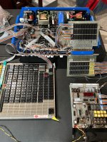
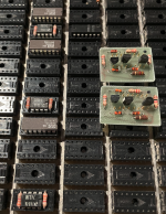
I updated my Kenbak prototyping setup so I could pull out more signals to try different things. In addition to the two wire wrap boards connected through the slot in the Kenbak's front panel that bring out the lights and switches (and some signals) to my "terminal" seen in the lower right of the 1st picture, I have a larger separate wire wrap board that I pull various ICs to for experimenting as seen in the lower left of pic 1.

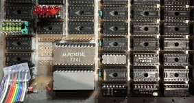
The 2nd picture shows the chips used for monitoring the L register for location 177 (7430), then capturing that location to the 74164 shift register to output to a 74100 8-bit latch (big gray chip that is hard to read), the lowest 4 bits of which are currently used as input to the 74154 to provide all the individual Enable lines for paging (I'm only using two right now). The Enable lines also power the LEDs so I can see which page is enabled.

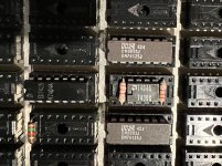
The third picture shows the added AMD 1404a (so I don't risk an Intel 1404a unnecessarily) surrounded by a couple of 74125 3-state buffer ICs. These buffers isolate the multiple 1404a ICs between the JDL1 and DL1 signals and are enabled from the 74154 lines to define the desired page for memory locations 200-377. They also provide the recirculation line to the 1404a that is not currently enabled. To expand this design, add more 1404a and 74125 (with a 7404 gate as needed to invert the Enable to the recirculation line).

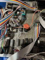
The 4th picture just shows how I used ribbon wire on headers to bring out the ICs to the prototyping board - no cutting of lines on the motherboard.

Some things I learned - don't try to change the MR (memory read) signal or you lose the ability to read the switches, unless you want to substantially change the architecture which I don't really want to do. It's not necessary to change MR anyway, with this approach. Location 377 works properly regardless of which page you're on. Also, no need to add another address line A8; again, too much change required and not sure it would even work. There doesn't seem to be an easy way to get my C1101 RAM working along with the serial memory so I'll just stick with adding more 1404a ICs. I'm sure trying to keep track of which DL1 is enabled in a program and how to manage the paging during runtime is going to be interesting.
 

Attachments

  • Kenbak_prototyping1.jpg
    Kenbak_prototyping1.jpg
    2 MB · Views: 12
  • Kenbak_prototyping2.jpg
    Kenbak_prototyping2.jpg
    854 KB · Views: 12
  • Kenbak_prototyping3.jpg
    Kenbak_prototyping3.jpg
    697 KB · Views: 11
  • Kenbak_prototyping4.jpg
    Kenbak_prototyping4.jpg
    1.5 MB · Views: 12
Attached is a link to a short video showing my replica running with paging working. I modified the "Example of Console Use" program in the Programming Reference Manual to add a bunch of extra steps to preserve and restore locations 200 through 203 while switching between pages 1 and 2. Seems quite a bit slower than the unmodified program, as expected. You can also see the page 1 and 2 LEDs on my prototyping board swapping back and forth quickly. (I see LED 6 is also flickering some, not sure what that is all about.). With this brute-force method, there is not much room left on page 0 after adding my page management steps to do anything else, so there is some work to do to make this a lot more efficient code-wise. https://www.dropbox.com/scl/fi/oqj0...0631.MOV?dl=0&rlkey=gg99lqig0nneloq7v9nzy556l
 
So, the extra program steps to preserve and restore 200 through 203 aren’t necessary. Carry and overflow are handled in the hardware without those steps. Also, I think monitoring the LC signal would be better than monitoring the whole L register for location 177 so I’ll try that in the future.
 
I now have 3 extra 1404A shift registers tied in to my Kenbak-1 replica, acting as memory pages 2, 3 and 4 for the octal range 200-377. I had to create and add two more level shifters using the same circuit as shown in the original schematics, because the extra shift registers were too much for the level shifters on the motherboard. I couldn't get anywhere near stable operation. Now, the system is more stable and enables the pages properly but it tends to halt at random times. This seems to be caused by the shift registers themselves - they are after all vintage pieces approaching 50 years old themselves. The program I'm using expands on the use of the B register to count up and display at location 200 - it also writes to and reads from most of the upper memory in a given page before displaying the result, as a more thorough way to test paging.
 

Attachments

  • 1404AonProtoBoard.png
    1404AonProtoBoard.png
    896.7 KB · Views: 6
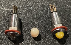
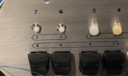
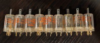
I have also started incorporating some micro lights on the front panel that I found during one of my many searches for vintage parts. These seem to match pretty closely the parts seen in online photos of the original Kenbak, as well as the description given in the manual. I found only white lens covers so I tried using translucent yellow paint on one of them - seems to look OK so far.
 

Attachments

  • MicroLightsonPanel.png
    MicroLightsonPanel.png
    404.8 KB · Views: 7
  • MicroLights.png
    MicroLights.png
    709.1 KB · Views: 7
Man, you've put a lot of work into this! Would be interesting to archive all of your work and schematics, and code examples if you were willing to share.

Those micro lights are amazing! Yes, they definitely look like the original lights. How many did you find? I've always tried to "decode" the lettering on the back of the lights to try to figure out who the maker was, figured it was probably a Japanese electronic light company (there were about 4 Japanese companies active around 1970). Never able to find an exact replica of the lights, in spite of hours of searching.

I know someone who really needs a replacement light for a broken one.

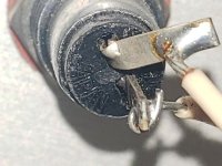
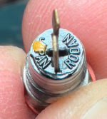
Below is a photo of an original Kenbak-1's light, which shows the word "Japan" but I could never make out the other letters. I actually took tons of these pictures, trying to see the name of the maker. Your lights are definitely the same as the original! Great find!
20230604_125727.jpg
- Thomas.
 
Last edited:
The word opposite JAPAN on my lights is RODAN. As you might image, an online search of RODAN and JAPAN yields tons of completely different images :). But there is an image of a similar light on the Surplus Sales of Nebraska website for a RODAN neon bulb. A bit different than mine, but I wonder whether a 5V incandescent T-1 bulb could be substituted for the neon? I was able to pick up enough of mine at Axman in St. Paul to populate my replica panel plus one more when I get around to building it, with a few spares.
 

Attachments

  • Screenshot 2023-08-03 at 2.11.57 PM.png
    Screenshot 2023-08-03 at 2.11.57 PM.png
    495.1 KB · Views: 1
Bummer. None left. I had previously looked all over Axman St Paul several months ago, even searched in other bins and behind bins, hoping one or two was mis-sorted or fell out. Today I checked Axman in Fridley, and Axman in St. Louis park, the two other locations. All stores had a similar selection of old lamps, but nothing like these. Bummer. Now that I know the maker is "RODAN" I can read it on my samples, but I had never heard of Rodan until today.

Good find! I'm a bit jealous, but good find!

- tj.
 
Back
Top