• Please review our updated Terms and Rules here

Model 1 Level 2 screen full of @

Dokken

Experienced Member
Joined
Feb 27, 2018
Messages
249
Location
TN
This junk machine has worked recently, but now only boots to a full screen of @ symbols. The only previous problems I had in getting it running had to do with vertical sync, but I had that working, displaying the level 2 basic screen and seemingly working. now just @.

Any pointers on what may cause this?
 
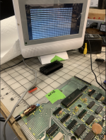
The address lines are outputs from the Z-80 used to specify memory locations. If any address line is not active (stuck on one state),
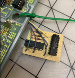
there will be 'garbage' (random characters) on the screen at boot. To check the address lines, remove the DIP Shunt at position Z3
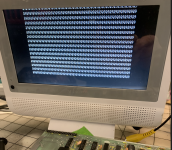
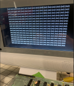
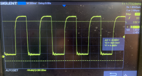
and power-up the system. If the screen fills with a pattern of “@9@9@9@9...”, then all the address lines A0 – A9 are good. The
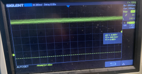
remaining address lines A10 – A15 can be checked for activity with a scope.

Why does it print @9@9?

It helps to know that. Here's why you get @9s. With the ROMs removed,
the CPU reads all 1's (that is, hex FFH) whenever it reads from the area
the ROMs are supposed to be in, because an open connection tends to
float to a 1 with this type of logic. Hex FFH is the RST 38H
instruction. So when the processor is turned on and fetches an
instruction from 0000, it gets a RST 38H (FFH). This makes it push 0001 on
the stack and jump to address 0038. At that address it reads another
FFH, so it pushes 0039 on the stack and jumps to 0038 again. Now it's in
an infinite loop. As the loop continues, the stack grows and grows,
going backward through memory. When it reaches the frame buffer between
3C00 and 3FFF, you can see it on the screen. It looks like a string of
@9's because the TRS-80 displays a 00 byte as an @ character, and 39 is
an ASCII 9.
OK. So the fact that you get @9's means that the CPU is working. The
data bus appears to be working correctly too, as if a data line were
stuck at 0 the CPU wouldn't be reading FF's, and if it were stuck at 1
the CPU couldn't be writing both @'s and 9's.


REF:

The @ is Hex 0x40 and SPACE is 0x20. If the screen is cleared by the ROM it should show 0x20
after the Sign On Message.

Remove the DIP Shunt at Z3, and Power ON. See what you get. It should be @9@9@9@9@9@9@9's


Larry
 
Last edited:
Thank you (again), Larry! Hope you're doing well this new year!

I had reviewed the diagnosis doc you referenced, and tried removing Z3 with the same results. a screen full of @.
 

Attachments

  • M1 Screenshot 2024-01-07 at 11.18.07 AM.png
    M1 Screenshot 2024-01-07 at 11.18.07 AM.png
    2.9 MB · Views: 18
Yes, Bruce is correct on the 32 characters per line. Check the 32/64 Characters per line (modsel signal)
on Pin 1 of Z43 74LS157. If it's stuck that could cause it.


Larry
 
Here are the Pages 28 and 29 OCR'd of the Tech manual for MODSEL.

Larry
 

Attachments

  • M1-p28.txt
    5.4 KB · Views: 3
thank you! Z41-1 is solid low. I'll look through the info above. thank you again!!
 
the 74175 Z59 seemed bad. 2nd picture is with Z3 removed, @9 as expected? 3rd picture is Z3 in, all on, 1@A@ repeating. progress, I guess.

and what is the function of the board in picture 1?
 

Attachments

  • m1 addon Screenshot 2024-01-08 at 2.59.55 PM.png
    m1 addon Screenshot 2024-01-08 at 2.59.55 PM.png
    2.2 MB · Views: 19
  • m1 z3 out Screenshot 2024-01-08 at 2.59.35 PM.png
    m1 z3 out Screenshot 2024-01-08 at 2.59.35 PM.png
    2.1 MB · Views: 21
  • m1 z3 in Screenshot 2024-01-08 at 2.59.23 PM.png
    m1 z3 in Screenshot 2024-01-08 at 2.59.23 PM.png
    2.9 MB · Views: 21
I'd think it's more of a D3 problem with Pin 13 of Z59 74LS175 being HIGH all the time, which causes
Pin 14 /Q being low all the time. Likely something in the Video RAM IC's Z48, Z47, Z46, Z45, Z61,
Z62, Z63, or associated IC's Z60 or Z44.

@A@1 vs @9@9
A = 1010
9 = 1001
1 = 0001

Bits 0, 1, and 3 changing at different times.

Larry
 

Attachments

  • MODESEL.png
    MODESEL.png
    86.3 KB · Views: 3
Download this Model 1 manual:

REMOVE the Z80 at Z40, REMOVE the 74LS175 at Z59

Let's check the D{0..7} data lines to see if we find a suspect.

Location to check voltage level with reference to GND

Z76 Pin 1 ?
Z75 Pin 15 ?
Z60 Pin 1 ?
Code:
          Z80
          PIN
D0        14    ?     Z76 Pin 11        Z68 Pin 9         Z68 Pin 10         Z44 Pin 7         Z44 Pin 6
D1        15    ?     Z76 Pin 13        Z68 Pin 3         Z68 Pin 2          Z44 Pin 5         Z44 Pin 4
D2        12    ?     Z75 Pin 13        Z68 Pin 5         Z68 Pin 4          Z44 Pin 3         Z44 Pin 2
D3         8    ?     Z75 Pin 5         Z68 Pin 7         Z68 Pin 6          Z44 Pin 9         Z44 Pin 10
D4         7    ?     Z75 Pin 7         Z67 Pin 9         Z67 Pin 10         Z60 Pin 9         Z60 Pin 10
D5         9    ?     Z75 Pin 3         Z67 Pin 3         Z67 Pin 2          Z60 Pin 7         Z60 Pin 6
D6         10   ?     Z75 Pin 9         Z67 Pin 5         Z67 Pin 4          Z60 Pin 5         Z60 Pin 4
D7         13   ?     Z75 Pin 11        Z67 Pin 7         Z67 Pin 6          Z60 Pin 3         Z60 Pin 2


Larry
 
sorry, got sidetracked with work stuff.

z40-14,15,12,8,7,9,10,13 = 2.5v
z76-11,13 = 4.2
z75-5,7,3,9,11 = 4.2
z68-9,3,5,7 = 4.2
z68-10,2,4,6 = 0.5
z67-9,3,5,7 = 4.5
z67-10,2,4,6 = 0.5
z44-7,5,3,9 = 4.5
z44-6,4,2,10 = 1.5
z60-9,7,5,3= 4.2
z60-10,6,4,2= 1.5
 
OK, I'm thinking you typed the following incorrectly: "thank you! Z41-1 is solid low."
I think you meant Z43 Pin 1............

I need you to Double check the 32/64 Characters per line (modsel signal) on Pin 1 of Z43 74LS157.
It is likely LOW all the time.

The Data Lines are exactly as I expected, but I've attached a file with a few more for you to check.
It's possible that 59 74LS157 could be bad, but I need the extra pins verified in the attached file.
(So far, every D{0..7} looks as it should.)

I need this extra data.

Larry
 

Attachments

  • Model1-DataLines.txt
    2.8 KB · Views: 1
thank you!

OK, I'm thinking you typed the following incorrectly: "thank you! Z41-1 is solid low."
I think you meant Z43 Pin 1............

I need you to Double check the 32/64 Characters per line (modsel signal) on Pin 1 of Z43 74LS157.
It is likely LOW all the time.

Z-43-1 is low all the time.

Z76 Pin 1 4.6
Z75 Pin 15 .2
Z60 Pin 1 3.9


Z80
PIN
D0 14 2.5 Z76 Pin 11 4.2 Z68 Pin 9 4.2 Z68 Pin 10 .5 Z44 Pin 7 4.5 Z44 Pin 6 1.5 Z59 Pin 4 = 4.5v
D1 15 2.5 Z76 Pin 13 4.2 Z68 Pin 3 4.2 Z68 Pin 2 .5 Z44 Pin 5 4.5 Z44 Pin 4 1.5 Z59 Pin 5 = 4.5
D2 12 2.5 Z75 Pin 13 4.2 Z68 Pin 5 4.2 Z68 Pin 4 .5 Z44 Pin 3 4.4 Z44 Pin 2 1.5 Z59 Pin 12 = 4.2
D3 8 2.5 Z75 Pin 5 4.2 Z68 Pin 7 4.2 Z68 Pin 6 .5 Z44 Pin 9 4.5 Z44 Pin 10 1.5 Z59 Pin 13 = 4.2
D4 7 2.5 Z75 Pin 7 4.2 Z67 Pin 9 4.5 Z67 Pin 10 .5 Z60 Pin 9 4.2 Z60 Pin 10 1.5
D5 9 2.5 Z75 Pin 3 4.2 Z67 Pin 3 4.5 Z67 Pin 2 .5 Z60 Pin 7 4.2 Z60 Pin 6 1.5
D6 10 2.5 Z75 Pin 9 4.2 Z67 Pin 5 4.5 Z67 Pin 4 .5 Z60 Pin 5 4.2 Z60 Pin 4 1.5 Z44 Pin 13 = 4.5
D7 13 2.5 Z75 Pin 11 4.2 Z67 Pin 7 4.5 Z67 Pin 6 .5 Z60 Pin 3 4.2 Z60 Pin 2 1.5 Z44 Pin 11 = 4.5

Also Z44 Pin 15 = 4.5
Also Z59 Pin 14 = 1.6

If Z59 Pin 13 is LOW Z59 Pin 14 should be HIGH, assuming we are getting the
/OUTSIG Z25 Pin 8 and the CLK Signal on Z59 Pin 9.
 
OK, I have attached the 74LS175 Datasheet and Pin 13 (D3 is LOW so when the Clock Pulse (cp)
happens the Out pin for /Q (Pin 14) is going to be HIGH (> ~2.5 VDC). And it isn't going High, so
either you aren't getting the cp (Clock Pulse) or the 74LS175 is defective.

Do you have an O'Scope or way to look for a Clock Pulse on Pin 14 of Z59?

Larry
 

Attachments

  • 74LS157.pdf
    332.3 KB · Views: 0
  • Model1-DataLines.txt
    2.8 KB · Views: 1
What are the Voltages on the following Pins with Z40 and Z59 removed??

Code:
Z40 Pin 20     Z23 Pin 2
Z40 Pin 22     Z23 Pin 1       Z23 Pin 3    Z22 Pin 2   Z22 Pin 3


Z25 Pin 9
Z25 Pin 10                                                                     
Z25 Pin 8


Larry
 
thanks, Larry.

on the clock signal Z59-6, it looks odd. z40-6 and z59-14 pics below with all chips in.

with Z40 and z59 out, voltages are:

z40-20 1.5
z40-22 1.5
z23-2 1.5
z23-1 1.5
z22-2 4.5
z22-3 4.0
z25-9 4.0
z25-10 0.2
z25-8 4.5
 

Attachments

  • z40-6 Screenshot 2024-01-15 at 12.11.15 PM.png
    z40-6 Screenshot 2024-01-15 at 12.11.15 PM.png
    3.3 MB · Views: 2
  • z59-14 Screenshot 2024-01-15 at 12.12.01 PM.png
    z59-14 Screenshot 2024-01-15 at 12.12.01 PM.png
    2.6 MB · Views: 2
For your Signal on Z59 Pin 14 /Q, expand your Horizontal sweep to get about 3-4 pulses on the screen,
and set your trigger for a Negative slope trigger. You should be able to sync to the signal on that
channel.

You can also check the Signal on Z59 Pin 9 the CLK Signal. If you are getting a good LOW going
Clock signal the MODESEL signal should be good.


Larry
 
There's a high chance that it'll be something simple!
Percussive maintenance seems to work and if that fails:

Someone would use their EPROM EMULATOR and load it with very short and simple test routines.
e.g. 18 FE or even C3 00 00 to start which will put the processor in a forever loop, then progress to loop that'll make the cassette port make a sound and later more complex routines such as writing a character to the screen memory F3 3E 45 32 00 3C 18 FE
From these tests you can observe the waveforms on your CRO.
 
Back
Top