• Please review our updated Terms and Rules here

Model 16 Renovation

shank

Experienced Member
Joined
Jun 14, 2018
Messages
192
Location
Pacific NW in the islands
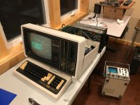
Some early notes on a Model 16 renovation.... resurrection? A little of both, I guess.

A friend had this sitting in his storage shed in Fort Worth and he'd bought it moons ago when it was surplussed from CPE, Computer Product Engineering. I was surprised he still had it! I'd had a rental storage shed full of these old machines, though they weren't so old back then, but who knew anyone would actually want them or that I might as well? Alas. That's the confession part of this thread and as I stand before you today I hang my head in shame. Please don't ask me what I did with them. I'll lie if you do.

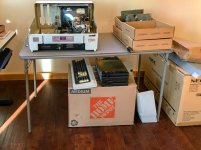
First question was how to ship it to the northwest and have it arrive intact. Answer is -- you can't, unless you disassemble it and then ship it. We decided to remove the drives and cards and ship them in separate boxes. Then the shell of the M16 was packed well to keep the CRT in position and the case from breaking. A week later the boxes showed up and everything arrived in fine shape.
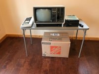
M16-Renovation-1625.jpg

The box under the table holds 2 15 Meg Hard Drive cases. Be awhile before I get to those. No bubbles shipped, but I have ST506 bubbles in storage--not that I expect they'll work.
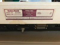
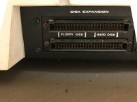
M16-Renovation-1628.jpg

M16-Renovation-1629.jpg

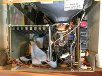
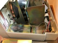
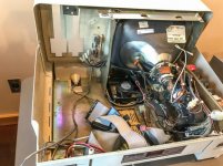
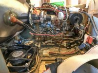
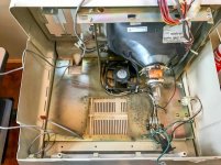
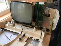
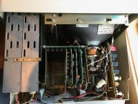
Quick look inside:

M16-Renovation-1626.jpg

M16-Renovation-1627.jpg

M16-Renovation-1693.jpg

Right off the bat there's a problem and it might be a show stopper....
M16-Renovation-1694-2.jpg

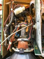
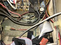
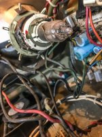
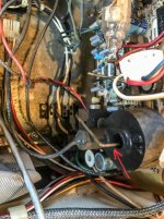
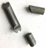
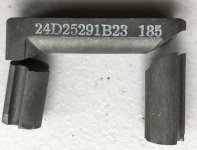
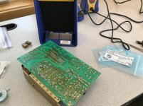
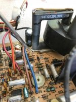
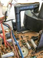
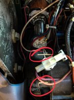
When I unpacked the M16 case I found a bit of metal that looked very familiar in the bottom of the box. Couldn't place it, but I kept it fortunately. It's the ferrite part of the flyback transformer on this Motorola video board. Somehow the brass rod broke releasing the ferrite in transit where it broke into 3 pieces. They're clean breaks and I have them all. I should be able to superglue it back together, replace it on the transformer and solder the brass rod back together. Ought to work fine. Close call!!

The cards are amazingly clean and most, maybe all from a quick look are very late revisions. That's a double edged sword, but they're clean and the only problem I found on visual inspection was a PAL hanging half way out of a socket. Looked to me like it had never been fully inserted.

Before anyone asks--I did not receive the Arcnet card. I have a box of boards somewhere and I might have one with those...

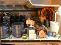
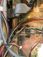
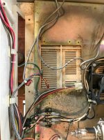
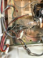
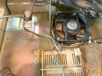
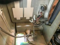
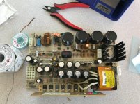
Otherwise, the unit, though intact other than the flyback, is filthy. I don't see mouse droppings, but I see a lot of dirt and dead bugs. First thing is to clean it up. I won't even attempt to fire it up until i change the 3 usual caps on the 11082 supply, clean it all up, put it back together, go through the 2 drives.... And then I'll see what happens. Oh, and I had to order a very long handled 1/4" nut driver. Can't work on one of these without one of those.
 
Continuing along...

M16-Renovation-1695.jpg

M16-Renovation-1702.jpg

M16-Renovation-1704.jpg

M16-Renovation-1706.jpg

M16-Renovation-1707.jpg

M16-Renovation-1708.jpg

During the disassembly, each subassembly I pull out is placed in a separate box along with screws and such in a baggie.

M16-Renovation-1709.jpg

As I disassemble I take photos of connections, orientations and like that. It's been quite a few years since I worked on one of these and I don't want to trust my memory. Why have to figure it out if I don't have to?

M16-Renovation-1782.jpg M16-Renovation-1784.jpg M16-Renovation-1790.jpg

M16-Renovation-1791.jpg
 
Getting down to it....

M16-Renovation-1792.jpg M16-Renovation-1793.jpg M16-Renovation-1794.jpg

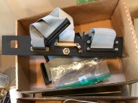
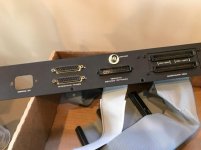
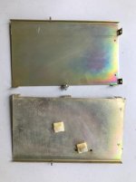
Back panel removed and cleaned. I've already done the card cage and its frame and I'll post a couple of photos of that tomorrow...

M16-Renovation-1798.jpg M16-Renovation-1799.jpg
 
Very cool, thanks for sharing! The 16A is my favorite because it can pretty much do everything a 6000 can (with some upgrades) but with a smaller footprint and is much easier to maintain.

A few things here I want to reiterate.

First, removing the floppy drives is probably the best step you can take to ameliorate potential shipping damage. Their concentrated weight just does not play well with the plastic case when thrown around.

Secondly, one of the the best things you can do to ensure you put it all back together is to take lots of pictures. You'll never remember exactly where every screw and wire went without visual cues. And there's no excuse with the capability of modern mobile phones!
 
Absolutely agree on the 16A vs 6000! Cooling is better too, unless you have the "turbo mod" on the 6000, but that's another story.

Since this is/was an Arcnet machine I want to mention something slightly tangential.... You know that there are 50 ohm and 75 ohm BNC connectors? I'm sure you do. Did you know that the center pin of those connectors used to be a larger diameter in the 75 ohm unit? This also applies to the 10-base-T BNC "T" connectors used with early Ethernet at RS and other places.... The problem comes into play when you have a 50 ohm system and someone plugs a 75 ohm male BNC into a 50 ohm female connector.. It spreads the center hole of the mating connector and from that point on the 50 ohm part is intermittent. This killed us in our networks, and some customer networks too. In house on the service end of things, we purchased all our connectors from National Parts and their stock was accidentally mixed--and at that time we didn't know about the size difference. I don't think anyone at Radio Shack knew. Drove us crazy! Anyone playing with old RS Ethernet cards or networking equipment be aware.

Fortunately, BNC connectors are standardized now to the same size regardless of impedance. Or, the better ones are at least.
 
6000 Turbo Mod? Is this different from the 68010 support?

Oh yes. Very different.

Engineering never talked to us in Technical Support about hardware design. It wasn't that we were super smart or that they weren't, but there's a difference sometimes in what looks like a good idea but isn't workable in the real world. One of the big issues with the Tandy 2000 was the horizontal option board design. When you stack hot boards on top of hot boards you have to really pay attention to air flow or you start to cook components. When we saw the same design in the Model 12 (and similar) we were worried. Our department systems, which were usually loaded with cards, began to overheat almost from day 1 and we soon were getting reports of customer problems as well. Spontaneous reboots to component failure...

To fix our systems we cut a large round hole in the back access panel and mounted an additional AC fan there blowing right into the card cage and across the cards and we verified that it worked with temperature probes. Problem solved, but the fan was loud and someone said it sounded like a "turbo" and so we referred to it in service as "the turbo mod." See Technical Bulletin 12/16B:10 for details. Unfortunately, there isn't a drawing of what the back panel looked like with the fan, but it's easy to visualize. Pretty snazzy... Not!

R&D got back involved at this time and proposed some additional modifications and that became the basis of the Technical Bulletin. Modification kits were stocked at National Parts. We sent a few basic kits out from our department to solve problems in the interim before the kits were ready at NP. You may see some variation and that's why.

The mod sort of blew the streamlined case work of these systems, but it did solve the problem.

But! Following the law of unintended consequences... One of our tech reps had the unfortunate experience of popping 2 CRTs while replacing the case on one of these systems in our lab one day.... This resulted in Technical Bulletin 12/16B:29.
 
Last edited:
Power supply caps changed and Motorola video flyback transformer repaired...

M16 Restoration-1815.jpg M16 Restoration-1816.jpg

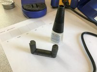
Superglued the ferrite back together:

M16 Restoration-1817.jpg

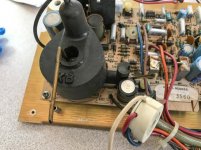
Now to replace it:

M16 Restoration-1818.jpg

If you look at the tip of the screwdriver in this photo, there's a nut underneath that the brass rod screws into. Once the solder repair is done I tightened the nut to hold the ferrite securely, but not too securely..

M16 Restoration-1819.jpg M16 Restoration-1821.jpg

I didn't get too wrapped up in making it fit like when it was new, only that it was all in place and secure. Also, didn't want to use too much heat around the ferrite.
 
just a little something coming up...

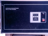
68K Mux-.jpg

this is one of two very large scale 68000 XENIX systems we ran in Technical Support.... it only looks like a communications multiplexer.
 
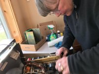
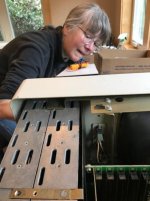
Once we had everything cleaned up we started to put it all back together.... Val worked on more of these than I did and she did part of the reassembly.

vsIMG_1836r.jpg IMG_1838.jpg IMG_1839-rot.jpg

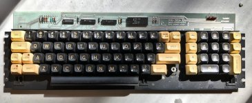
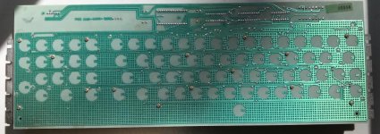
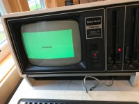
Keyboard is pretty beat and we did glue some broken bosses back in on the case. Mainly opened it up to make sure there wasn't anything metallic rolling around in there shorting the keyboard--we were hearing the broken plastic. We did this before first applying power.
kybd-IMG_1846.jpg kbd-IMG_1847.jpg

Attached the DVM to +5V and fired it up....

vs-IMG_1841.jpg

Junk and retrace lines on the video, video board squealing, no indication of trying to boot and reset did nothing... 5V was good though, and so were the other voltages...

Time to fire up the scope and look around. First were noise checks on the power supply and they were good. It really looked like the Z80 wasn't running. How to find out without an extender card?

IMG_1871r.jpg

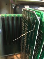
Grabbed some resistors and tacked them to the video card in the cage -- easiest to get to with plenty of room. Picked +5V (to make sure I had 5V in the cage) and a random data line. If I could see data on the scope then the Z80 should be running. 5V was good but no data activity. I had just enough room to wedge a scope probe between the CPU card and the cage side and grab a clock. Clock is running with good amplitude and frequency. Pulled the board, removed and reinstalled jumpers and the main socketed devices just to be sure corrosion wasn't a problem. No change.
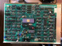
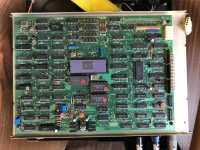
(Note to new trouble-shooters on these machines. If you don't have an extender card it's OK to tack leads to specific signals of interest on the board/s and run them out to where you can grab them with a scope, DVM, or whatever you're using. I didn't need to be too careful with these, but if I were running leads out between cards I'd of course use insulated wire and keep the lead lengths to a minimum. If needed you can further insulate card from card with copier paper or whatever you have at hand.)

Ok... Probably reset.... First we made sure that it wasn't the front panel reset switch by manually shorting the pins on the CPU card. No change. Time to watch reset with the scope. Wedged another probe in and reset is not working. No power on reset so nothing starts up. Manual reset doesn't do anything.

Just to be sure, today I swapped in a Rev B CPU card:

IMG_1870p.jpg

I'd seen a CPU card for a reasonable cost on ebay last week and had a feeling I might need it... Arrived today and I dropped it in. "Insert Diskette" comes up. The video needs adjusting but isn't squealing and the front panel reset actually reset the machine. Once I find my extender cards, or buy a new one if I can't find them, I'll start looking at the Rev D CPU card. It'll be easier with an extender...

Haven't tried reading a diskette yet...

We used to have 3M come in and do static safety demos every year or two. Part of what they'd do is demonstrate how static can kill a device out right, but can also degrade a device cumulatively causing it to fail later on after the static hit. They'd set up a test device, usually a transistor or op amp, measure its performance and then zap it. Next they'd measure it again and if the device wasn't outright failed, it was easy to see that although it was functioning, it was degraded. Zap it again and measure and then we'd see more degradation in performance. Finally, it would fail.
 
Tacking on the leads as extended test points is a great hack I never considered if you don’t have an extender card.

It looks like both of you are having a good time revisiting your past experiences. Thanks again for sharing!
 
Not a lot of time today, but did try and boot the system. Drive spins, but doesn't step. Drive, cable, or FDC? I'll try and get to it later.

Did have time to open up the hard drive units--no bubbles and surprisingly clean:

IMG_1874-hd1-r.jpg IMG_1875-hd2-r.jpg

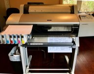
I'm not sure what I'm going to do with them. While looking at those there was time to print out some schematics... Rev A board and I have Rev A schematics.

IMG_1878-epson-r.jpg

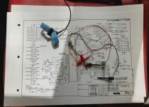
These clip leads are really good for hooking test points between boards when no extender card is available--or when you want to watch multiple signals on different boards and don't have enough extenders. They're small enough to sit between the boards. I had to go hunting for mine, but I think these are pretty common and not expensive.

IMG_1879r.jpg
 
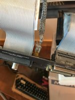
Had some time and made a bit of progress... Time to pull the drives out and do a swap (I hated swapping drives in the Model 16). I'd also forgotten how much I disliked the tight quarters where we jammed all the ribbon cables between the cards and the case--sheesh! And, I'd forgotten how much I liked working on the Z80/68K systems.

I've been enjoying reading this forum as I've had time to and listening to the podcasts. It was a fun and sometimes wild ride in the Towers when this gear was new. That was then, though, and for as long as you've been putting these systems back together, some real basket cases evidently--much worse than anything we had to contend with, and making them run like new again, I have to say that you're the experts at this now.

I'll post again down the road when I've got this one reading a diskette and running some diags.
 
Quick update... Not much to report. System boots, drives work now... Mem II runs well when I can coerce the keyboard into cooperation. Foam pads are toast and I'm waiting on a kit to fix it up. My flyback repair seems to be holding.

One of the TM-848-2 drive handles is seriously broken and I'm playing around with 3D printing a replacement. More playing than serious, but we'll see.. I don't own a 3D printer so I'll need to send any design out for printing.
 
Back
Top