Upcoming Events:
- VCF South West - June 14 - 16, Davidson-Gundy Alumni Center at University of Texas at Dallas
- VCF West - Aug 2 - 3, Computer History Museum, Mountain View, CA
- VCF Midwest - Sept 7 - 8 2024, Schaumburg, IL
- VCF SoCal - Mid February 2025, Location TBD, Southern CA
- VCF East - April 2025, Infoage Museum, Wall NJ
-
Please review our updated Terms and Rules here
You are using an out of date browser. It may not display this or other websites correctly.
You should upgrade or use an alternative browser.
You should upgrade or use an alternative browser.
Model 4 Font
- Thread starter taos23
- Start date
Jay Newirth
Experienced Member
Could it be a defective character generator chip (just a wild guess) .... contact Ian -- he may have a better answer
shank
Experienced Member
I don't have a schematic handy, but looking at your screen shot... If i'm counting right, it appears that the character generator only outputs a 7th character column of dots (counting left to right) on the lower case w and m characters (in your screen shot--but other characters may be affected, like graphic characters). That's your clue, I think. Like Jay suggested, the problem could be right around the character generator... data line, buffer... something like that... might be the character generator.
If you don't have a scope, an inexpensive logic probe will help you see activity on data and address lines. you can probably build one for less than a cup of coffee at your favorite emporium. Amazon has them, even! I kept one of the RS versions in my tool kit for years. Fast when I didn't want to drag out a scope and just needed to see activity through buffers/inverters and like that. So, active data on one side of a buffer but zero activity on the output: bad buffer, or a component shorted to ground just after perhaps... A simplification, but you get the idea.
The good thing about video problems is that you can actually see the issue.
ldkraemer
Veteran Member
Petrofsky
Experienced Member
I was going to guess the problem was in the line from pin 17 of U19 (the font ROM) to pin 33 of U17 ("Vidarray", the video support gate-array chip).
But if you're getting the same missing-column-7 behavior in graphics characters, then that sounds like a problem in the Vidarray. The Vidarray generates the graphics characters internally, and sends all 8 columns of them out the same pin (pin 19), so I don't see how the fault can be in the lines external to the chip. Are you sure you're seeing this behavior with a chip in U17 that works fine in another system?
(We are talking about a gate-array motherboard, right? With a big socketed 40-pin DIP at U17?)
Can you post a pic showing what happens with graphics characters, and with reverse video?
Petrofsky
Experienced Member
Btw, here's a picture of the font in the standard Model 4 character generator (part 8049007). You can see column 7 is pretty sparsely used, and appears in only 4 ASCII characters (_ m w ~). Leaving a blank column on the left AND the right in most characters avoids illegibility in the first or last character of a section of text in reverse-video.


TRS-Ian
Veteran Member
Is U23 a socketed 24-pin chip on your motherboard?
TRS-Ian
Veteran Member
That's a non-gate array board so make sure when people are advising you chip numbers and schems you are dealing with the right board.
U23 is the character generator so try a different one. U21 is your video SRam and can be replaced with any 6116 they are all the same.
Also on your non-gate mobo the 68045 (U47) is your CRT controller, its responsible for positioning the characters on the display and does funky things when it's not right.
Check each of these chips and especially their sockets and if you still have no luck then its time to hit the schems and a scope.
Cheers,
Ian.
Petrofsky
Experienced Member
Ah, so you do not have a gate-array motherboard (and the 14-pin DIP in U17 is unrelated to the problem).
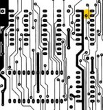
From your photos, it appears all your major components are working fine, but columns 0 and 7 of each character cell are getting wire-ANDed together. Those are the inputs on pins 2 and 14 of U11 (the 74LS166 shift register). With the power off, try checking those two pins with an ohmmeter. If there's no resistance, that may be your problem.
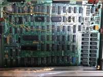
Looking at the traces in the technical manual, I'm guessing the problem is right underneath U11, where the trace going into pin 14 comes close to a trace running up the center, which is connected on the other side to pin 2. It's the yellow spot in the pic below. The horizontal DIP-24 in this pic is U23, the vertical DIP-16 with the yellow spot is U11.
If the traces are being bridged, then separating them may fix the problem. Alternatively, the problem may be internal to U11 and it needs to be replaced.

Petrofsky
Experienced Member
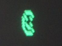
To test my theory that columns 0 and 7 are being ANDed, I'll predict that even through column 7 doesn't show up in m and w characters, it shows up fine in the happy face character, in which the 3 pixels in column 7 also appear in column 0. Try booting to Model III BASIC and entering "POKE 15487,196" to put a happy face in the upper right corner.
Petrofsky
Experienced Member
Hey Larry, when I tried to respond to your private message I got "ldkraemer has exceeded their stored private messages quota and cannot accept further messages until they clear some space."
There were two Model 4 Technical Reference Manuals. The second one, the "TRS-80 Model 4/4P Technical Reference Manual", Cat. No. 26-2119, is the one you're thinking of. It covers 4 and 4P, gate-array and PAL (non-gate-array), but with just the cut up schematics and no circuit traces. On the plus side, it includes lots of data sheets for components, and includes some details about the five custom gate-array chips.
The earlier manual, the "TRS-80 Model 4 Technical Reference Manual", Cat. No. 26-2110, covers only the original (two-crystal) PAL board, but it includes full schematics and traces.
You can find both at archive.org. Here's a link straight to the PAL board component-side circuit trace.
ldkraemer said:Where can the Model 4 Non Gate array Manual be located that has a good set of schematics attached?
The manuals I have found and downloaded just have cut up sections with no full schematic.
There were two Model 4 Technical Reference Manuals. The second one, the "TRS-80 Model 4/4P Technical Reference Manual", Cat. No. 26-2119, is the one you're thinking of. It covers 4 and 4P, gate-array and PAL (non-gate-array), but with just the cut up schematics and no circuit traces. On the plus side, it includes lots of data sheets for components, and includes some details about the five custom gate-array chips.
The earlier manual, the "TRS-80 Model 4 Technical Reference Manual", Cat. No. 26-2110, covers only the original (two-crystal) PAL board, but it includes full schematics and traces.
You can find both at archive.org. Here's a link straight to the PAL board component-side circuit trace.
Last edited:
ldkraemer
Veteran Member
Alan,
Thanks, I was busy trying to send you another PM when I discovered the full inbox.
Larry
Thanks, I was busy trying to send you another PM when I discovered the full inbox.
Larry
Petrofsky
Experienced Member
The earlier manual, the "TRS-80 Model 4 Technical Reference Manual", Cat. No. 26-2110, covers only the original (two-crystal) PAL board, but it includes full schematics and traces.
I should mention that taos23 doesn't have the original two-crystal PAL board (labeled "8709296 REV A"). He has the later single-clock PAL board (REV B or C). Most of the changes are in the upper left quadrant. I think the tracing in the area we're looking at (around U11 in the upper right) is about the same. From what I can see in your photo, it looks the same.
ldkraemer
Veteran Member
taos23,
I've written up a PDF document that is on my Dropbox account with the following link: (Anyone with link can access for some duration.....)
https://www.dropbox.com/sh/8zcx0rhgzu58rc1/AAA24YpJ4f5Dw9Hjzbzs5FeWa?dl=0
Download everything at that link. 4 items.
Print the PDF after viewing, and have your yellow marker ready to mark the places I have in RED on the PDF. Those are the KEY PLACES.
I've tested the basic program on my Model 4 so I know 100% it works.
It shouldn't take long to locate the problem socket, trace, IC, or bad solder joint.
If it's a Tandy Power Supply (I'd have to go look at the exact model number) be sure to turn the Power Supply over and VERIFY
that the PINS that are soldered to the Supply have a good solder flow and no circles around the pins or weak looking solder joints.
That was a problem with the Tandy Power Supplies.
Yes, those are a PAIN, until you know the secret. Get yourself an old wooden pencil that is about 5" long.
Lay the wooden pencil in the bend of the flex cable and hold the flex cable tight to the wooden pencil
as you remove the flex cable. Insert the cable the same way, by wrapping the cable around the wooden
pencil and insert the cable into the connector. It's easy to do now!.
TROUBLESHOOTING M4:
If you just use an OHM meter to OHM the Trace (and IC socket) for the Char Gen IC to the Shift Register IC
I'm 99% sure you will locate your problem. It could be a cold solder joint, bad IC Socket for Char Gen IC,
cracked or broken trace, or bad Shift Register IC or bad IC socket for Shift Register.
If you have an O'scope or Logic Probe you should be able to trace the signal by running the Basic Program.
It shouldn't take more than 20 minutes to isolate the problem.
Thanks for the update.
Larry
I've written up a PDF document that is on my Dropbox account with the following link: (Anyone with link can access for some duration.....)
https://www.dropbox.com/sh/8zcx0rhgzu58rc1/AAA24YpJ4f5Dw9Hjzbzs5FeWa?dl=0
Download everything at that link. 4 items.
Print the PDF after viewing, and have your yellow marker ready to mark the places I have in RED on the PDF. Those are the KEY PLACES.
I've tested the basic program on my Model 4 so I know 100% it works.
It shouldn't take long to locate the problem socket, trace, IC, or bad solder joint.
I'm restoring a model 3 as well and it seems to have a power supply issue.
If it's a Tandy Power Supply (I'd have to go look at the exact model number) be sure to turn the Power Supply over and VERIFY
that the PINS that are soldered to the Supply have a good solder flow and no circles around the pins or weak looking solder joints.
That was a problem with the Tandy Power Supplies.
I'm always reluctant to pull the motherboard because of those thin flex cables--I ruined one!
Yes, those are a PAIN, until you know the secret. Get yourself an old wooden pencil that is about 5" long.
Lay the wooden pencil in the bend of the flex cable and hold the flex cable tight to the wooden pencil
as you remove the flex cable. Insert the cable the same way, by wrapping the cable around the wooden
pencil and insert the cable into the connector. It's easy to do now!.
TROUBLESHOOTING M4:
If you just use an OHM meter to OHM the Trace (and IC socket) for the Char Gen IC to the Shift Register IC
I'm 99% sure you will locate your problem. It could be a cold solder joint, bad IC Socket for Char Gen IC,
cracked or broken trace, or bad Shift Register IC or bad IC socket for Shift Register.
If you have an O'scope or Logic Probe you should be able to trace the signal by running the Basic Program.
It shouldn't take more than 20 minutes to isolate the problem.
Thanks for the update.
Larry
Last edited:

