• Please review our updated Terms and Rules here

Model 4 monitor issue

itripn

Member
Joined
Jan 10, 2022
Messages
12
Hey all, I’ve done a bit of searching on a monitor issue I’m having on my model 4, but haven’t come across any actionable information.

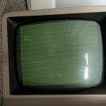
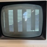
This monitor was working fine and one day I powered on and got this situation. Changing the contrast and brightness has little effect on the lines but I’ve the brightness up pretty high in the attached photo in order to emphasize what I’m seeing. The system still works and I can just barely see the actual text on the screen.

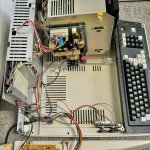
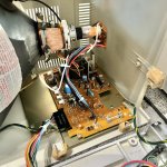
I’ve visually inspected caps throughout and don’t see any obvious issues but I’m pretty wary of the voltages on the video board.

Any tips on how to troubleshoot this issue would be much appreciated.

Cheers,
Ron
 

Attachments

  • IMG_2271.jpeg
    IMG_2271.jpeg
    1.6 MB · Views: 25
Looks like the brightness is ok, but maybe the contrast pot is faulty. With the power off check the contrast pot with a multimeter, resistance should go from 0 to 500Ohms when turned. Make sure the connection back to the board is also ok.
 
Thanks @Kool65 I'll take a look -- turning the pot does impact the display, but I'll get a MM on it and check the resistance range and report back.

Cheers,
Ron
 
@Kool65 I finally got around to checking this POT over the weekend -- it does indeed go from 0-500 (~512) ohms smoothly as I turn it. I also traced wires back to make sure there are good connections back to the monitor board and all looks okay.

If you have any other suggestions for chasing this down, I'd appreciate it.

Cheers,
Ron
 
Turn the brightness down so you can't see the retrace lines on the display.

1. Look at your Power Supply to see if it is a TANDY Power Supply with a single row of Pins
sticking up from the PCB. If it is remove it and look at each Pin to make sure there are no
small rings around each pin. If you locate a poor solder joint, re-flow the solder on each
Pin. Replace the Power supply.

2. Boot into Cassette Basic by having Power OFF.
Depress the Break Key and keep it depressed. Turn on Power. When you see text on the screen,
release the BREAK Key and depress the Enter Key twice.

If you are in BASIC type in ?MEM then the ENTER Key.
You should see 48082 or something close.


Larry
 
Thank you Larry -- now that it's all disassembled, I will be able to take a look at this tonight. FWIW, it does boot to basic and otherwise works great. It's just this brightness/contrast issue.

Cheers,
Ron
 
Hi Larry, I went through your steps last night. I did find at least two cold solder joints on the connector pins, so I reflowed the solder across all pins to be sure. Visual inspection of the rest of the power board showed everything else looks good.

Unfortunately this did not change the behavior of the monitor and I'm seeing the same results as before. But super glad to know I have good connections at the power connector now.

Note that previously I did replace the two RIFA caps on this board, as they blew shortly after I received the unit and turned it on :)

And to reiterate, everything else seems to work fine, I can boot to basic, and with a little work boot a floppy (the drive doesn't hold the disk tight enough so I need to push some pressure on the mechanism).

Thanks again for the troubleshooting advice. I guess my next thought is to remove the monitor board (carefully) and inspect it for bad solder joints. I don't see obvious signs of leaking caps but can better check that with the board out.

Cheers,
Ron
 
OK, in 64 Character Mode do the rows and columns of the characters look sane?
Or do they have the same problem as the 80 Column mode?

How about a picture?

While in cassette basic with a screen full of characters, try putting it in 32 Character Mode by using
SHIFT RIGHT ARROW This should be 32 Characters

to exit tap clear Key or the CLS <ENTER> command
Is the 32 Character display correct?

Larry
 
If you can bother to post the schematic, I can more than likely tell you what is wrong with it, or how to fault find it.

The first question being, can the brightness control cut off the beam (blank the raster scan) or not ?

(good move not doing anything to it yet, like replacing parts, until the fault is diagnosed)
 
Hugo,
Thanks AGAIN for chiming in. I have the Non Gate Array Model 4's Schematic on my PCloud account at:

The Gate Array Model 4's Schematics are at:

Non Gate Array Model 4
Model_4_Technical_Reference_Manual_1983_Tandy_Corporation.pdf has the Video info on page 143 of the pdf.

I'm not sure if this is a Gate Array Model 4, or a Non Gate Array model 4. On the Non Gate array Model 4's
most had C120 (Upper left section of Motherboard as viewed from the back) to adjust the Memory Sync timing.
It's easy to tell by looking how the RS-232 Cable connects. If it's vertical = Non Gate Array , and if it connects
horizontal it's a Gate Array.

You need the find the memory sync trim cap on the motherboard and adjust it back into spec. It happens in nearly all
non-gate 4s and 4Ps that use the trim cap to adjust memory timing. On the 4 its cap C210, on the 4P I'm not sure
(C231 seems to ring a bell), but it does the same job. Why has memory timing got anything to do with one of the video
modes? Beats me, but it just does..

Ian


Larry
 
If you can bother to post the schematic, I can more than likely tell you what is wrong with it, or how to fault find it.

The first question being, can the brightness control cut off the beam (blank the raster scan) or not ?

(good move not doing anything to it yet, like replacing parts, until the fault is diagnosed)

Hi Hugo, thank you for jumping in, really appreciate it.

I can turn the brightness down until the monitor is objectively dark.

I've attached a few photos here, one being the monitor with the contrast turned all the way up, and the brightness turned to a point where I feel the text is about the right brightness and contrast, although obviously the horizontal lines still persist. If I turn the brightness down until I cannot see those lines, the text is completely gone.

I also attached two photos of the inside of the machine, which I doubt are particularly helpful, but just in case. I am happy to pull it apart more and report back on what I see on the motherboard, etc. This one unit has Nov 1984 stamped in side of it.

I have another Model 4 with Oct 1983 stamped inside of it. It's monitor (which is blue hue, btw) worked perfectly, but when I boot it, I get screens full of random characters (perfectly displayed). I've gone through a few debug cycles with it, replacing the RAM, CPU and Video chip with no luck. The two units are different enough inside that it would seem using parts from one to get the other working is not a particularly straight forward operation, if even possible.

Thanks again, I'd love to get one of these units working, they're such amazing machines from that time!

Ron
 

Attachments

  • IMG_3157 Large.jpeg
    IMG_3157 Large.jpeg
    260.5 KB · Views: 10
  • IMG_3159 Large.jpeg
    IMG_3159 Large.jpeg
    494.9 KB · Views: 9
  • IMG_3160 Large.jpeg
    IMG_3160 Large.jpeg
    426.3 KB · Views: 9
Hi Hugo, thank you for jumping in, really appreciate it.

I can turn the brightness down until the monitor is objectively dark.

I've attached a few photos here, one being the monitor with the contrast turned all the way up, and the brightness turned to a point where I feel the text is about the right brightness and contrast, although obviously the horizontal lines still persist. If I turn the brightness down until I cannot see those lines, the text is completely gone.

I also attached two photos of the inside of the machine, which I doubt are particularly helpful, but just in case. I am happy to pull it apart more and report back on what I see on the motherboard, etc. This one unit has Nov 1984 stamped in side of it.

I have another Model 4 with Oct 1983 stamped inside of it. It's monitor (which is blue hue, btw) worked perfectly, but when I boot it, I get screens full of random characters (perfectly displayed). I've gone through a few debug cycles with it, replacing the RAM, CPU and Video chip with no luck. The two units are different enough inside that it would seem using parts from one to get the other working is not a particularly straight forward operation, if even possible.

Thanks again, I'd love to get one of these units working, they're such amazing machines from that time!

Ron

Here's a shot of the other unit -- despite my phone's inability to deal with the sync, the monitor perfectly displays all that random garbage... Hitting reset does not seem to change any of the characters being displayed. However, turning it off and on typically results in a very different pile of garbage, in some cases only displaying a couple of characters in the upper left with the rest of the screen being blank.

Thanks,
Ron
 

Attachments

  • IMG_3161 Large.jpeg
    IMG_3161 Large.jpeg
    302.1 KB · Views: 8
I’ve been staring at this board for 15 min and I cannot find a trim cap anywhere. Leading me to question my sanity or basic understanding of electronic components, both of which are likely questionable even on good days.

Given the horizontal RS232 I’m assuming this is a gate array model.

I’ve attached a photo if anyone can confirm
or confirm or deny my lack of sighting. Thanks!

IMG_3189.jpeg
 
To close out this thread, I ended up purchasing a motherboard off eBay for the blue phosphor unit and swapped it out, and that unit now works perfectly. The only downside is that it is the unit with no floppy drives (or appropriate power supply). I'll work to add a SD card based floppy to it in the future.

So I will be looking to sell (or give away for cost of shipping) the other unit hopefully to someone who can do a better job than I have at diagnosing the display problems.

Thanks for the kind attempts at all the help evident in this thread, I very much appreciate it!

Ron
 
Back
Top