• Please review our updated Terms and Rules here

Model 4 Non-GA Garbage at power on

wdatkinson

Experienced Member
Joined
Nov 21, 2007
Messages
54
Location
Noblesville, IN
New to me unit. Was hand delivered, not shipped. Reported to have worked fine prior to boxing it up. I picked it up yesterday and drove home. Unboxed this evening and set it up on a desk. Upon power on, I see the following:

trs80 m4 junk-forum.jpg

Subsequent power ones result in similar behavior. Every now and then drive 0 spins up like it's going to attempt to boot, nothing shows on the screen and the drive stops after a few seconds. I never see a Diskette? prompt. Reset does not work. Holding Break at power on to drop to M3 Basic also does not work.

I haven't used M3's or M4's since middle school and I just turned 47. I do repair other machines and am ok fixing this unit as opposed to returning it, just need an idea of where to start.

Thanks!
 
wdatkinson,
the first thing to do is Open the case and look for a Tandy Power Supply. If there is a Tandy Power
Supply with a row of Round Pins, remove the Power Supply and then turn it over and check for
COLD Solder Joints. Look at each Pin with a magnifying glass and look for small circles around
each Pin. Re-Flow the Solder around those pins. I use Kester 63/37 Solder for the PCB's. Even
if it looks good, I'd re-flow all Round Pins on a Tandy Supply.

But, be very careful when you lift the top of the case STRAIGHT UP and then lay it on it's Left Side
so you can unhook the video cable and ground wire. You want to stand so you hover over the top
and look down through the air vents and carefully raise it straight up, while watching the neck of the
CRT so it doesn't get broke. Once you remove and replace it once you will know what to do.

If the Solder Joints are good on the Tandy Power Supply or it's an Astec, then I'd remove the metal
shield and have a look at all the IC's in Sockets. Make sure they are all seated properly, as that can
cause problems.

Next on my list would be creating a Z80 NOP tester and then replacing the Z80 with the Z80 NOP tester.
You can test all the Address Lines with it, as they route through the PCB. You will need an O'Scope for
those tests. That should check about 80% of the computer. All that would be left is the Data Bus and
it's buffers etc.

The good thing is that it has nice crisp, clear video, so you know the video section is working. It's just
displaying garbage, which is likely because the CPU is running amuck.

If you can get it to power up in Basic, then you can do a few tests to see what is going on.

Do you have the Service manual downloaded yet?


Larry
 
But, be very careful when you lift the top of the case STRAIGHT UP and then lay it on it's Left Side
so you can unhook the video cable and ground wire. You want to stand so you hover over the top
and look down through the air vents and carefully raise it straight up, while watching the neck of the
CRT so it doesn't get broke. Once you remove and replace it once you will know what to do.

Since you haven't worked on a Model III or 4 before I wanted to emphasis this...watch the neck through the drive openings or vents the whole time you are lifting or replacing the top.

Also, if you have a spare Z80A lying around you can try swapping it out. I have seen Z80s go bad a number of times.
 
Having just ruined a CRT let me second the cautions about lifting the top case. The back of the CRT, where the electron gun board sits, can catch on wires running to the motherboard, which is at the rearmost of the case. If anything, when lifting up the top, which contains the CRT and its driver board etc., you want to make sure the case is moving forward slightly to clear those wires. If there is any resistance stop and reassess.

-CH-
 
I've watched multiple videos on YouTube and every one stresses catching the CRT neck when removing the top case. I will be very very careful.

I do have an O-Scope. I have not downloaded the SM yet, honestly I haven't looked for it, but will give it a goog.

I'll start working down the list and report back. I just had surgery on my right hand, so I'm a bit gimpy, so I might take a day or two to get through everything.
 
wdatkinson,
One other thing you need to do while you have the computer apart, is to check and see if you
have Tanton TM-100 Floppy Drives installed. If so, open the floppy drive doors, and shine a
light up into the hinge area of the door assembly and make sure there is a full length Brass
Rod for the hinge point. You might find two short white Nylon pins instead. If you have the
two short white Nylon pins, they need to be removed and a 3/32 Brass Rod inserted.
I have them available if you need one or two. They aren't expensive, but I had to
purchase a pound of Rods, and they were shipped from Florida.


Larry
 
FWIW, I have an Astec PSU in my Model 4 NGA and it also had cold solder joints that I had to reflow.

If it still misbehaves once you check that, and all your voltages are good, I'd start poking around the CPU with an oscilloscope. There is obviously power getting to the CRT analog board (that was my problem with the Astec PSU), and the mainboard is obviously sending *something* to the analog board.

This leads me to believe that maybe the CPU isn't initializing properly. What we see on the screen might be random garbage in the video RAM, which ought to be cleared as soon as the CPU initializes. I'd check the reset line and the clock, and then poke around some address lines to see if the CPU is actually running.

Maybe it could still be a PSU issue though. Those oldskool RAM chips sometimes require some pretty gnarly voltages, so yeah.

That being said, I don't really know what I am talking about most of the time, so I may be full of crap. But if I was the one poking around at it, that's the next thing I'd check, anyway. ;P

Good luck!!!!!!
 
I've watched multiple videos on YouTube and every one stresses catching the CRT neck when removing the top case. I will be very very careful.

You can peek in through the disk drive openings and see if you are snagging any wires, if your light is good enough.
 
Ok, I've finally healed up enough I could clean off the bench and take a look at the 4D.

The power supply was an Astec. Even so, I pulled it and under the microscope found a few fractures around the pins, so I re-flowed all of them.

After an initial check, the problem persisted, so moved on to the socketed chips. I pull each, and sprayed some DeoxIT in each socket then replaced each chip.

I did not do the RAM yet. Could RAM cause my problem? I can certainly do that next. I also have a NeoLoch RAM tester, but not sure if it covers whatever chips are in these beasts.

I have several pictures, but the forum doesn't re-sized on the fly, and I don't feel like messing with GIMP to resize all the photos.

So as of now, I'm still seeing the same issue and have:
1). Reflowed pin connector on PS
2). Pulled, DeoxIT'd, and reseated all chips except RAM.

I have 2-3 C128's laying around. Do they contain the same Z80? If not, I can see about sourcing one online. I'll also do some checking for a Z80 NOP tester and see what's involved there.
 
Been through all 16 RAM chips and all test OK according to my NeoLoch. The first back was Motorola ceramic chips and the second bank was NEC's.... I'm guessing due to a later upgrade.
 
1). Yes I have an oscilloscope. That's what I used to check the pins on the Z80. Also observed activity on the various pins of the RAM.
2). Holding break down yields garbage. Perhaps different garbage. Pressing enter does not seem to change the display.
 
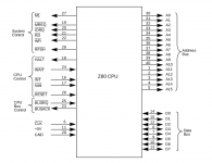
OK, Since you are not getting to the ROM's, and the CPU appears to be running amuck
you need to VERIFY the Control Signals that are inputs to the CPU's Pins:

Pin 16 - /INT
Pin 17 - /NMI
Pin 24 - /WAIT
Pin 25 - /BUSRQ
Pin 26 - /RESET

If none of these is being held LOW, then move to checking the Address Lines. The easiest
way to do this id to locate a known good SPARE Z80 CPU and make yourself a NOP Tester.
To do this bend Pins D{0..7} out enough so they will not go into the IC Socket on the Motherboard.
Then Solder a wire from D{0..7} to the GND pin on the CPU. Now insert the NOP TESTER Z80
into the Motherboard 40 Pin Z80 IC Socket, making 100% sure no D{0..7} Pin contacts the
40 Pin IC Socket on the Motherboard.

Power up the Computer and check A{0..15} across the Motherboard. You will have A0 being a
a square wave of some frequency. A1 will also be a square wave at 1/2 the frequency of A0.
A2 will be a square wave 1/2 the frequency of A1. Repeat for remaining Axx Lines. This will
check about 80% of the computer. What will remain is the Data Bus.

This assumes you have VERIFIED the +5 VDC Power Supply and the +12 VDC Power Supplies
along with checking for a Good Clock Signal from the OSC circuit.


Reference the attached PNG for the Z80.

Larry


Z80_CPU.png
 
I have several pictures, but the forum doesn't re-sized on the fly, and I don't feel like messing with GIMP to resize all the photos.

I like to use imgur.com when various fora won't allow my high-rez photos.

I second what ldkraemer said, and I think he knows a lot more than I do about this.

FWIW (and hopefully I am not full of poo when I say this), it may be worth checking that the power-on-reset circuit is working as it should. It should assert the reset signal for a moment when you first power on the machine. If they implemented it with a simple R/C circuit, a bad capacitor there could prevent it from working, and if it's screwed up then nothing will initialize right when you power up. This *may* also apply to a soft reset via the button, but I am not sure. Depends on how they implemented it.
 
wdatkinson,
One other quick thing you can try is to remove The ROM(s) one at a time. Then, lay the ROM on a table
or non conductive surface. Orient the ROM so the Pins are pointing to the right. Take a semi-sharp
pocket knife, and easily scrape along the pins moving from the IC Body to the end of the Pins. If there
is any corrosion or dark areas on the pins it should easily scrape off. Repeat for the other side (inside)
of the ROM so both insides of the ROM are clean. Then, do both outsides, so they are clean.
Re-insert the ROM with the orientation correct. Repeat for the other ROM(s).

Then try a Power up.

Larry
 
I would swear I'd measured these before, but they seem to have been lost.

Pin 16 - 0VDC
Pin 17 - 5.12VDC
Pin 24 - 4.40VDC
Pin 25 - 5.04VDC
Pin 26 - 4.64VDC

Pin 6 - 2.04MHz

So obviously Pin 16 sitting low is an issue.


OK, Since you are not getting to the ROM's, and the CPU appears to be running amuck
you need to VERIFY the Control Signals that are inputs to the CPU's Pins:

Pin 16 - /INT
Pin 17 - /NMI
Pin 24 - /WAIT
Pin 25 - /BUSRQ
Pin 26 - /RESET

If none of these is being held LOW, then move to checking the Address Lines. The easiest
way to do this id to locate a known good SPARE Z80 CPU and make yourself a NOP Tester.
To do this bend Pins D{0..7} out enough so they will not go into the IC Socket on the Motherboard.
Then Solder a wire from D{0..7} to the GND pin on the CPU. Now insert the NOP TESTER Z80
into the Motherboard 40 Pin Z80 IC Socket, making 100% sure no D{0..7} Pin contacts the
40 Pin IC Socket on the Motherboard.

Power up the Computer and check A{0..15} across the Motherboard. You will have A0 being a
a square wave of some frequency. A1 will also be a square wave at 1/2 the frequency of A0.
A2 will be a square wave 1/2 the frequency of A1. Repeat for remaining Axx Lines. This will
check about 80% of the computer. What will remain is the Data Bus.

This assumes you have VERIFIED the +5 VDC Power Supply and the +12 VDC Power Supplies
along with checking for a Good Clock Signal from the OSC circuit.


Reference the attached PNG for the Z80.

Larry


View attachment 64374
 
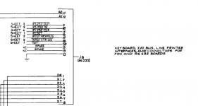
I pulled J8 from the board and powered on. Same garbage and 16 is still low.

Located both RP1 and RP2 and pulled the board and reflowed all 16 solder joints.

Pin 16 is now high, along with all the others. Still garbage on the screen though. No boot to M3 BASIC, etc.
 
Back
Top