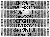
I recently got a Model I (with Level II ROM daughter board, lowercase mod and some other curiosities I'll describe below) that was badly busted and banged up in transit. The exterior is problematic but most of the internals seem in-tact from my initial review, aside from the plastic risers and screw pegs. I've spent the weekend attempting to get anything out of it as it initially had no power at all, and have made really good progress.
After reseating all the socketed chips, testing the RAM and swapping one bad 4K, as well as adjusting the 12V and 5V (via R5 and R10) so they are within spec (-5V as well), I am to the point where there are visuals and it seem the ROM is good. BASIC itself seems to work in that I can CLS, print, etc.
The first problem was that the visuals were mostly indecipherable... Faded, horizontal tearing, smearing, very poor fidelity. I have confirmed the display is good as I had been using it on a different machine. (NOTE: While composing this post, I found an adjustable resistor connecting R27 to R28, and altering that cured the blur/tearing so the text is looking sharp again, albeit dimmer than it typically should be even at max contrast on the monitor and still probably an area to review more closely if I get everything else operational.)
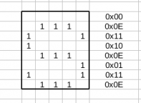
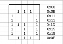
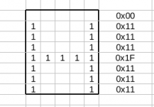
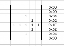
The real problem is that all characters except for the top row are entirely corrupt, many of which resemble something not even part of the character set. However, the top row of numbers, - and * all work and display fine.

Any pointers on where I could start troubleshooting this, checking voltage on certain chips or similar? Unfortunately none of the VRAM is socketed so testing or replacing is more tedious, same with the character ROM (and I have no replacement for the character ROM).
If I remove the Z3 shunt or L2 BASIC ROM connector, it produces pulsating squares.

If I remove the Z71 shunt, it produces pulsating @/9 but they are combined and blurred, like it is double buffering or something.

Sometimes I'd get the garbage screen that'd alter between lower and higher resolution styles when I'd power off and on. But this was rare, typically it boots right up to BASIC.

A few times when I've turned it on, it started full of gibberish but then each character tile (usually starting from the bottom-right) would be replaced with a reverse L (that is also the same symbol that is entered if I type 'a'), one at a time. I caught the tail end of one such occurrence on video here, but note this is a very rare occurrence:
Toggling the lower/uppercase mod does not change any of these characters, except it then shows a box (looks like a smiley) where the current cursor is at, instead of just blank space.

A second unlabeled toggle switch connects to pin 7 of Z41 and pins 10-11 of Z42. A bodge wire runs from pin 11 of Z42 to pin 1 of Z30. When this toggle is active, any characters or white elements of the screen become black blurs... I have no idea. (Screenshot is of screen of boxes again with Z3 removed, but toggle set.)

This set also has a "Data" key, which is a user-added extra key. It has two wires, one runs to Z2 Pin 4 (Keyboard PCB) and the other to Z4 Pin 10 (Keyboard PCB). It doesn't seem to do anything, but was built with an LED underneath it (which also never lights).

Thank you for any assistance!
After reseating all the socketed chips, testing the RAM and swapping one bad 4K, as well as adjusting the 12V and 5V (via R5 and R10) so they are within spec (-5V as well), I am to the point where there are visuals and it seem the ROM is good. BASIC itself seems to work in that I can CLS, print, etc.
The first problem was that the visuals were mostly indecipherable... Faded, horizontal tearing, smearing, very poor fidelity. I have confirmed the display is good as I had been using it on a different machine. (NOTE: While composing this post, I found an adjustable resistor connecting R27 to R28, and altering that cured the blur/tearing so the text is looking sharp again, albeit dimmer than it typically should be even at max contrast on the monitor and still probably an area to review more closely if I get everything else operational.)
The real problem is that all characters except for the top row are entirely corrupt, many of which resemble something not even part of the character set. However, the top row of numbers, - and * all work and display fine.

Any pointers on where I could start troubleshooting this, checking voltage on certain chips or similar? Unfortunately none of the VRAM is socketed so testing or replacing is more tedious, same with the character ROM (and I have no replacement for the character ROM).
If I remove the Z3 shunt or L2 BASIC ROM connector, it produces pulsating squares.

If I remove the Z71 shunt, it produces pulsating @/9 but they are combined and blurred, like it is double buffering or something.

Sometimes I'd get the garbage screen that'd alter between lower and higher resolution styles when I'd power off and on. But this was rare, typically it boots right up to BASIC.

A few times when I've turned it on, it started full of gibberish but then each character tile (usually starting from the bottom-right) would be replaced with a reverse L (that is also the same symbol that is entered if I type 'a'), one at a time. I caught the tail end of one such occurrence on video here, but note this is a very rare occurrence:
Toggling the lower/uppercase mod does not change any of these characters, except it then shows a box (looks like a smiley) where the current cursor is at, instead of just blank space.

A second unlabeled toggle switch connects to pin 7 of Z41 and pins 10-11 of Z42. A bodge wire runs from pin 11 of Z42 to pin 1 of Z30. When this toggle is active, any characters or white elements of the screen become black blurs... I have no idea. (Screenshot is of screen of boxes again with Z3 removed, but toggle set.)

This set also has a "Data" key, which is a user-added extra key. It has two wires, one runs to Z2 Pin 4 (Keyboard PCB) and the other to Z4 Pin 10 (Keyboard PCB). It doesn't seem to do anything, but was built with an LED underneath it (which also never lights).

Thank you for any assistance!

