• Please review our updated Terms and Rules here

NEC PC-8001 trying to make RS-232 cable

voidstar78

Veteran Member
Joined
May 25, 2021
Messages
695
Location
Texas
As mentioned elsewhere (here), the RS232 pinout for the NEC PC-8001 is noted here:

The header for this RS-232 is actually internal to the system, and my understanding is a PC-8062 cable was used to tether the pins outside the system. I've not yet found any photos of that cable, so I've tried to make one.

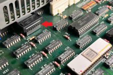
I got a 16-pin DIP with a cable attached, and that fits perfectly in the socket inside the NEC PC-8001 like so:
1711258446267.png

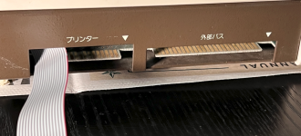
I ran it below the power supply, and out one of the rear slots: (note, I think the RED side of the cable is actually pin 16, not pin 1)

1711258529180.png


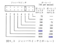
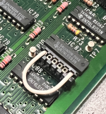
Other translated info is that there is a "jumper" used to specify the baud rate. I believe it is this one, and connected across 1-6 is 300 baud (which is fine for starters):
1711258660671.png


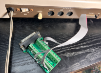
Next, I didn't want to assume the pinout of the internal 16-pin DIP SOCKET was the same as the pinout of the PC-8062 cable. So for starters, I'm probing the socket 16-pins like this:
1711258780534.png


I'm testing the continuity and voltages between all these pins, will report results in next post.
 
Last edited:
Here's the initial results. As expected, the specified PC-8062 isn't 1:1 to that pinout of that internal socket.

The voltage test in the middle was after the system had been on for about 10min.

In the voltage test on the right, the values in parenthesis are the actual measured values.

1711259933105.png

During power on, that "3.6V" pin would sometimes be higher (4.4 - 4.8), a few times was over 5V. (even as the system was idle) But mostly it would hang around 3.6V. Are any RS232 pins floating when not connected?

Not sure what to try next. If we assume the 6 expected grounds are covered by the 6 detected grounds, then 3 power lines (-12, +12, 5) - that leaves 7 lines left to try to figure out the order.
 
Last edited:
When I am stuck in this situation, I use an oscilloscope and probe pins while you type on keys... the 12volt are signals ready(-12) not ready(+12), and the 5volts are floating waiting for something to pull them high or low.
 
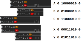
Forgot I had a 32-channel logic analyzer. Got it figured out and have a WiModem232 working with the PC-8001 with its built in TERM command. Will post more notes tonight.


But for starters, I found the TX pin and recognized the correct ASCII sequences getting sent - by entering term mode and tapping keys as suggested (start bit, 8 data bits, stop bit), keeping in mind the databits are "reverse" from what we'd normally expect.

1711324722854.png
 
Last edited:
Ok, confirmed it all works! And here's the video... Happy BBS'ing now on your NEC PC-8001 !!! (but no ANSI and no backspace support, so it's a little bit of a rough ride)

Just GND/TX/RX, enough to communicate. Didn't find RTS/CTS pins, so this might not work for data transfer (KERMIT, ZModem type stuff).


No special chips needed, just a 16-pin DIP socket connector with a cable ribbon, then just tape 3 wires to a standard DB25.
 
Last edited:
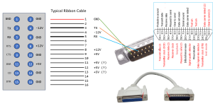
I'll get notes on a more concise wiring diagram tonight. That little 16-pin ribbon cable, the pins are "crisscrossed" (not like a regular IC DIP) so gotta be careful there.
 
Think the internal 16-pin DIP socket is like the pinout expressed for the PC-8062 cable. I goofed in thinking the ribbon cable followed the "normal" IC pinout (1-8 on one side, then 9-16 wrapped around to the other side). Doesn't invalidate any finding, and I realize to keep that "socket extender" easy to make, it's pinout is a lot simpler than that (that's how I meant it "crisscrosses").

Note how normal DB25 RS232 doesn't have any voltage. Then also note Pin1 just depends on how you want to make the cable - you could attach directly to the WiModem232, or go through an intermediate cable (even a DB9), but doing so "reverses" the pin (depending on how you look at it). Anyway, maybe the following references will help make sense to others in making their own cable - just those first three are the minimum necessary (that should correspond to 1-3-5 on the ribbon). Three wires to xmit bits across systems, just like the old SAGE in 1958.

1711417339163.png
 
Last edited:
I've also picked up a 8001 mk II just to compare it.

Here are some follow up notes on the PC-8001 mk II :

- When in terminal mode, GRAPH+B is key to swap back to BASIC.


The User's Manual for PC-8001 mk II on archive.org is in Japanese. But luckily the mk II that I got, the connectors at the back are labeled in english.

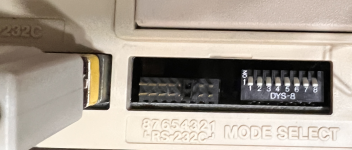
One main difference with the MK II is that a DB25 connector is on the back now for RS232, so you can adjust baud rates without opening the system.
1711607537901.png

I'm still not entirely understanding the x16 vs x64 clock divider and what decides that - but my system seems to be using the x16 column (because it was set of PIN3 and was doing 300 baud).

1711607547540.png


I haven't messed with MODE SELECT. I recall there is an option to revert back to more "pure" PC-8001 emulation.

I wasn't able to run the built in TERM past 600 baud. At 1200 baud it was getting noticeable character drops (especially during scrolling the terminal screen) and anything faster then that was just non-responsive (even though the jumpers are going up to 9600 baud).

Anyhow, next to these baud rate jumper is the actual RS232 25-pin header. Can plug the WiModem232 directly into that port, or go through a parallel cable. And the built in ROM TERM does work (just for now, seems limited to 300/600 baud).
 
Back
Top