i am so sorry, i recently redid my site and neglected to forward everything, that document now lives here http://wiki.rsx11m.io/DEC/PDP8/DECmate_cableHaving no luck accessing this URL, even using the Wayback Machine :-<. Is there a replacement link?
| VCF West | Aug 01 - 02 2025, | CHM, Mountain View, CA |
| VCF Midwest | Sep 13 - 14 2025, | Schaumburg, IL |
| VCF Montreal | Jan 24 - 25, 2026, | RMC Saint Jean, Montreal, Canada |
| VCF SoCal | Feb 14 - 15, 2026, | Hotel Fera, Orange CA |
| VCF Southwest | May 29 - 31, 2026, | Westin Dallas Fort Worth Airport |
| VCF Southeast | June, 2026 | Atlanta, GA |
-
Please review our updated Terms and Rules here
You are using an out of date browser. It may not display this or other websites correctly.
You should upgrade or use an alternative browser.
You should upgrade or use an alternative browser.
Need advice on DEC RAINBOW adapter
- Thread starter VERAULT
- Start date
jdreichard
New Member
- Joined
- Oct 27, 2018
- Messages
- 9
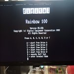
I wanted to follow-up on this thread. Miraculously, I have the DEC Rainbow running. Not RAM, not ROMs, but the oscillator! Upon checking with an oscilloscope, I discovered that the pin that should have been outputting 24.07342 MHz for the rest of the system was dead as a doornail. So here's how I brought my Rainbow back to life:
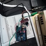
1. I used an Arduino and the Adafruit SI5351A clock generator chip to generate the right frequency (25 * (28 + (11101/12500))/30).
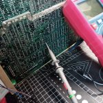
2. To make this easy, I soldered the SMA connector to the board and then hooked up my oscilloscope probe with a BNC coupler.
3. I hooked onto the clock's pin on the bottom side of the main board.
4. Booted up the Rainbow and... viola! No Massive Hardware Failure!
5. Keyboard error of course.
6. I hastily constructed the LK201 (of course, like everyone else, the LK201 I have is dead as a doornail) emulator on another Arduino Nano.
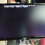
7. It kinda works --- and sometimes gets me past the system check to the main screen.
8. I can get to the Terminal, but the emulator incessantly and erratically issues key repeats. It may be a software issue.
9. Onward and upward.
But, the Rainbow lives!
I found a supplier of 24.073 MHz crystal oscillators. I will replace it when they arrive and update this (and cross threads) on the progress.
Thanks!
Josh
1. I used an Arduino and the Adafruit SI5351A clock generator chip to generate the right frequency (25 * (28 + (11101/12500))/30).
2. To make this easy, I soldered the SMA connector to the board and then hooked up my oscilloscope probe with a BNC coupler.
3. I hooked onto the clock's pin on the bottom side of the main board.
4. Booted up the Rainbow and... viola! No Massive Hardware Failure!
5. Keyboard error of course.
6. I hastily constructed the LK201 (of course, like everyone else, the LK201 I have is dead as a doornail) emulator on another Arduino Nano.
7. It kinda works --- and sometimes gets me past the system check to the main screen.
8. I can get to the Terminal, but the emulator incessantly and erratically issues key repeats. It may be a software issue.
9. Onward and upward.
But, the Rainbow lives!
I found a supplier of 24.073 MHz crystal oscillators. I will replace it when they arrive and update this (and cross threads) on the progress.
Thanks!
Josh
Attachments
FYI....i am so sorry, i recently redid my site and neglected to forward everything, that document now lives here http://wiki.rsx11m.io/DEC/PDP8/DECmate_cable
wiki.rsx11m.io refused to connect Google managed to have a cache of it at least.pbirkel@gmail.com
Veteran Member
How do I get to that cache? I'm getting a site-timeout this AM and unfortunately the IA hasn't yet indexed/archived anything :-<.FYI....
wiki.rsx11m.io refused to connectGoogle managed to have a cache of it at least.
mark0x01
Experienced Member
A picture might be worth 1000 words, but only if you have one, but I didn't save the picture, so here are the words I saved.
Hope this is what you need. I made one, but the Rainbow has been packed away to repair another day.
You can make up an adapter to allow you to use a standard monochrome composite monitor and the LK201 keyboard.
Pin 12 - monochrome composite video signal
Pin 4 - video shield ground
Pin 5 and 6 - ground
Pin 7 and 8 - 12V
Pin 14 - RX data keyboard
Pin 15 - TX data keyboard
P1 = 15 pin
P2 = kbd
P1-6P2-3 conductor Gnd
P1-8P2-2 conductor+12v
P1-14P2-1 conductor rx
P1-15P2-4 conductor tx
rj pin
1 = blk --- 15
2=red gnd --- 6
3=grn +12 --- 8
4=yel --- 14
i am having some migration issues, here is the original post in its entirety
Code:
References:
* [NetBSD: LK201 Interface](https://www.netbsd.org/docs/Hardware/Machines/DEC/lk201.html#pinout)
* [DEC Rainbow VR201 DB15 Connector Pinout](http://www.larosse.net/pc100/dec100-vr201-cable.html)

What you will need
===================
* [DB15-F](https://www.amazon.com/uxcell-Breakout-Connector-Solderless-Terminal/dp/B07MMN55NM) and [RJ11](https://www.amazon.com/dp/B097SPR48M) terminal blocks, or the tools to make something more permanent. The pinouts that follow worked for me with these Amazon products but you will want to verify correct pinning yourself.
* A standard VGA cable and some spare shielded wires
* A wire stripper
* <b>(optional)</b> [VGPerfection OSSC](https://videogameperfection.com/products/open-source-scan-converter/). The OSSC provides a clearer display in my experience, but you might not need this, especially if you have a CRT

How to do it
============
Cut one end off the VGA cable and strip the plastic to expose the wiring. You will only need three: VGA green (should be green), its ground (copper wire typically wrapped around it), and the VGA ground wire (should be black). Verify this yourself using a multimeter to ensure you have the right wires.

Next, strip both ends off your spare shielded wires, we will need four for the RJ11 portion. The RJ11 pinout assumes you have the connector oriented as in the NetBSD document linked above, included here just in case:

<pre>
<code>
    |----- data -< -------------------------------------------|
    |    |-------- >- Power -----------------------------|    |
    |    |    |------------- GND -------------------|    |    |
    |    |    |    |------------- <- data -----|    |    |    |
   -------------------                        -------------------
  | "    "    "    "  |                      | "    "    "    "  |
  | L    V    G    D  |                      | D    G    V    L  |
  | K    +    N    E  |                      | E    N    +    K  |
  | ->        D    C  |                      | C    D         -> |
  | D             ->  |                      | ->             D  |
  | E              L  |                      | L              E  |
  | C              K  |                      | K              C  |
   --               --                        --               --
     |             |                            |             |
      --         --                              --         --
        |       |                                  |       |
         -------                                    -------

     Looking into the                       Looking into the DECstation
     LK201 Connector                                 Connector
   (Socket on keyboard)                        (Socket on DECstation)

</code>
</pre>

Wire everything up to the DB15-F block using the following pinout:

<pre>
<code>
VGA green -> DB15 pin 12 (mono out)
VGA green gnd -> DB15 pin 4 (mono gnd)
VGA gnd -> DB15 pin 5 (gnd)
RJ11 pin 1 -> DB15 pin 15 (kbd rx)
RJ11 pin 2 -> DB15 pin 6 (gnd)
RJ11 pin 3 -> DB15 pin 7 (+12v)
RJ11 pin 4 -> DB15 pin 14 (kbd tx)
</code>
</pre>

Take care not to swap pins 2 and 3 on the RJ11, or your LK201 will eat +12v and fall over dead. Verify your pinout with a multimeter before plugging the cable into your LK201. VGA goes to the OSSC, HDMI (or whatever) to your machine, and you're good to go. No more VR201 cataracting!