• Please review our updated Terms and Rules here

Need help with TRS-80 PT-210 Data Terminal

Just put one of these together, and there is an alignment issue for the right angled 16 pin connector, its more proud of the board than the standard right angled connector allows. So we need to find a different header that achieves alignment. The board slides down a "slot" into the correct place, so another header appears to be the only option.

Also, there is a blocking pin in mine, can others confirm that is present in other PT-210's?

From eyeballing this a little bit more closely, it appears that the header is 1 row too low into the connector, so it would have to be 2.54mm (guess?) higher to hit the target.
 

Attachments

  • pt-210-internal.jpg
    pt-210-internal.jpg
    517.4 KB · Views: 4
Last edited:
Well if you looked at the photos I posted of my rd-232 card you would see it was missing that pin. So a block makes sense.
 
Bit more analysis, the alignment of the pins is everso slightly off, hope this picture shows:

pt-210-alignment.jpg
 
Oh, that's cool! Printed a copy of the board? I'm not even mad at all, I'm impressed and totally supportive 👏 Especially in UK, to which shipping would be a slow pain.

Yeah, I based it on photos, and I didn't even realize it slid into a slot (as I don't have one myself). Not too shabby alignment for a "phoned-in" design :)

I had a lot of trouble finding a connector that gave any spacing off the board. But knowing it's about 1 pin off gave me an idea...

TSW-1xx-08-G-T-RA.JPG


This, and remove the 3rd (inner/top of the right-angles) row of pins. It also pushes the connector forward (towards board edge) a bit though (if placed in current footprint), and it's a fair bit more expensive ($3 ea).

Can we get a more zoomed-out view of the setup?
How's the alignment look to the switches & port through the cover?
Wondering if I need to nudge the board outline (the whole board) over a bit, or shift the connector alone...

edit: Over in a different category, this might be worth a try as well... https://www.digikey.com/short/3qh9v74d - only other part I've seen with "elevation" of that sort. Might work, but a pain to order. Manufacturer's site is more flexible but all "out of stock": https://mlelectronics.com/part/BSTCR-1
 
Last edited:
Where are you in the UK as I’m up near Liverpool. Happy to work along with you. I love the 3 row idea.
 
Wish I was. I'm in US which is why I figure you went for fabbing it yourself instead of waiting for me to get mine made, haha ;)

Any chance you (or anyone) have any better ideas about the spaced board interconnect header?
 
The challenge there is not so much about small orders, but rather finding any part that's not flush against the board. Out of a catalog of 100,000+ parts, few to none on Digi-Key are gapped off the board the way the RS-232 board's connector is. Makes it quite difficult to find something to line up. It seems to be off by a full pin position's depth, something that's nearly unobtanium in today's parts catalogs.

One option (aside from the expensive 3-row part, and removing the 3rd row) might be to find "long lead" parts (ones with a larger lead length, but the same insertion length on the mating pins), and locate an appropriate spacer to place between the component and the holes. I'll look into that as well.

@Amardeep-AC9MF has the completed board, and done some mods to (hopefully) make the connector line-up best it can. From there, we ought to know soon enough if the board actually works enough to make a next version :)
 
index.php


Pic for reference of the issue at hand :) 
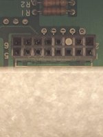
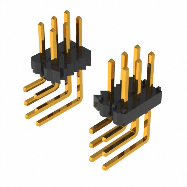
That's the original board (in the photo), showing a significant spacing of the pins away from the board. Modern connectors almost all sit nearly flush against the board (just enough room for the housing to clear, but otherwise flat against the board). Including the one I used...
 
@Tarkie101 Looking closely at your photo, it looks like you have the board inserted upside down. The header is 36mm from one side, and 38mm from the other. If you turn it around and insert it, the connector footprint and the machine socket should line up better.
 
It fits well and I only detect a fraction of a mm bend in the pins, which might not even be the result of misalignment. I will have some time tonight to try out communications.

I think it would engage more robustly if the pins were a couple of mm longer, past the edge of the board.
 

Attachments

  • IMG_20240111_163654205_HDR.jpg
    IMG_20240111_163654205_HDR.jpg
    809.7 KB · Views: 16
  • IMG_20240111_164359132_HDR.jpg
    IMG_20240111_164359132_HDR.jpg
    114 KB · Views: 17
Ok, it took longer than I anticipated to circle back around to testing this. A number of things demanded attention and then the arctic blast. But after reviewing the schematic diagram to understand the cabling I successfully hooked it up to a desktop computer.

The two switches must be set properly. One selects between RS232C and Modem. The other is labeled COMM/TERM and really selects DCE/DTE. So after figuring that out and setting both sides to the same communication settings..IT WORKED!

My machine has a mostly bad keyboard so I could only test sending '3' and '9' but it receives and prints everything the computer sends. I would call this design valid and functional. A slightly longer pin header maybe 2-3mm past the edge of the card would allow it to engage more robustly. The one I have as seen in the picture in the previous message is only about 1mm past the edge and it barely engages the socket connector.
 
How awesome is that! Perfect. I've got some ideas to make the connector work better, and it looks like the exposed expansion board area on the case is very flexible... at minimum, I can consider this a viable/good drop-in reproduction, but in the future it also opens up capabilities for, e.g., a USB interface, ESP32 modem, who knows what else. Good stuff.

With that, I'll get to work on cleaning up the rough connector fit, and get 'em listed! :) Thanks for testing it, that's very cool.
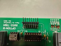
Count me in on your future endeavors of esp32 etc!!! Im interested for sure.
 
Was browsing Ebay for something else when I see a familiar shape on the thumbnails... could it be? yes it was!, immediately ordered one.

Life events threw me out of the retrocomputing bit for a while and late 2023 I started to gain speed back up, the RS232 option for the PT-210 being one of "those projects" left behind.

As soon as I am done recaping my CM-8 (CoCo 3 monitor) the PT-210 gets next slot at the workbench. My CM-8 went all crazy on me shortly after acquiring a WiFi modem with which I was making my BBS rounds on the CoCo 3, too much fun. Now I'll have a chance to try OS9 LII from the PT-210 onto the CoCo 3 :)

Thanks so much FalconFour for the effort on building up the RS232 option board Kudos!
 
Haha. And I'm going a step a bit further ahead, too... trying not to let my interest in the PT-210 die off so soon... I'm trying to get an ESP32 board for it going, too. We've already got lowercase transmit/receive working in a ROM mod, too (adding lowercase mapping, and adding lowercase bitmap font - all of which was already spaced-in the ROM, just blanked-out!). See over here: https://forum.vcfed.org/index.php?t...s-232-board-reproduction-rom-hacking.1246685/

Plan is to keep them around in perpetuity on eBay... long as I'm around, they'll be available. I hope. Minor tweaks and improvements here and there as new revs are built.
 
Back
Top