NeXT
Veteran Member
We're now a year shy of Sony's first entrance into the consumer portable video camera market fifty years ago. In 1967 they unveiled the DVC-2400 (Also known with the DVK and VCK models, but otherwise the same thing). A black and white Vidicon pickup video camera with a matching portable tape deck called a Portapak. At $1250 in 60's dollars it wasn't cheap and you could barely call it portable but it was a start and at least it was compatible with their existing line of Video Tape Recorders, like the CV-2000. Sony proudly advertised the portable Video Tape Recorder, the DVK-2400, as one of the lightest (only 10lbs without the batteries) and cheapest units they had made. Indeed it was both however with some serious corner cutting.

The VTR is record-only. You cannot play back anything. You also have no fast-forward or rewind. Attached inside the lid is a hand crank you slipped into holes on the spools and manually wound the tape. Its resolution was also not too impressive either. At seven Inches Per Second one reel of tape held approximately 20 minutes of footage with 220 horizontal lines of resolution. Literally you turned it on, pointed at your subject, pressed RECORD, then ran back to the tape machine at home to play it back.
About two months ago one of these kits came to my attention for a reasonable price. It wasn't apparently working but with the service manuals included I couldn't resist.
>>IMAGE<<
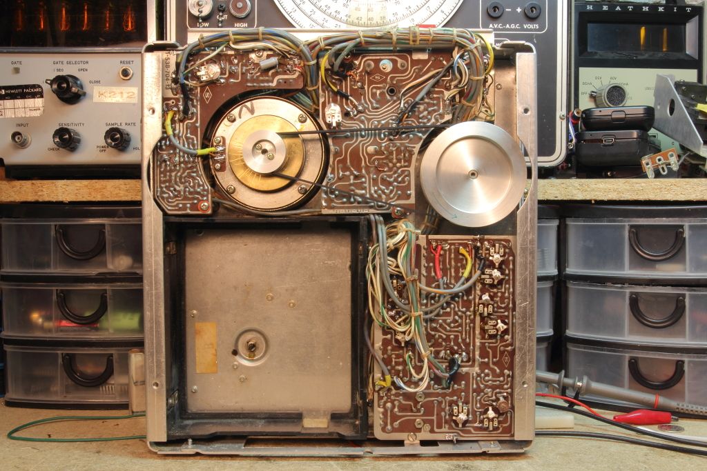
Indeed it wasn't the most mint condition artifacts but indeed it was rather complete. Cables, manuals, service documentation, AC supply, tapes and spools and even the little aluminum clip that holds the microphone was in the box. The only thing it didn't come with was the microphone, hand crank and the presumably now long dead lead acid batteries. Indeed however it did not work. A required 9v for running some of the logic was not being created and the drum was not spinning. The camera also had some issues but we'll get to that later. Without yet glancing at the schematics I assumed that the drum motor was brushless and some form of stepping action was required to bring it up to speed. After several hours of poking around it was discovered that the 9V regulation circuit was in fact two transistors and a potentiometer. While one transistor tested good, the other did not.
>>IMAGE<<
>>IMAGE<<
Simply put, these transistors are O L D. Sourcing a replacement can sometimes prove to be rather hard. While the DVK-2400 proudly stated it was an all-transistor design (41 transistors and 21 diodes, to be exact) it rarely used anything more than the 2SC401. This transistor has been out of production for a number of decades. In fact, even the substitutes have also been out of production for a while now. Thankfully because of how simple the circuit was the modern and extremely common 2N3904 made a perfect substitute. After some soldering and a careful voltage adjustment we had our 9V....but still no drum rotation.
At this point I began to better review the schematic and the exploded diagrams of the head assembly. Indeed there was something unexpected.

Both diagrams indicated that deep within the drum and the motor there was a set of brushes. While there was a simple biasing circuit used to get the motor up to speed after hunting down the cabling for the motor a simple resistance check found that the circuit was open. Great. Either the brushes had worn or a winding had opened. Regardless, getting in was not going to be fun.
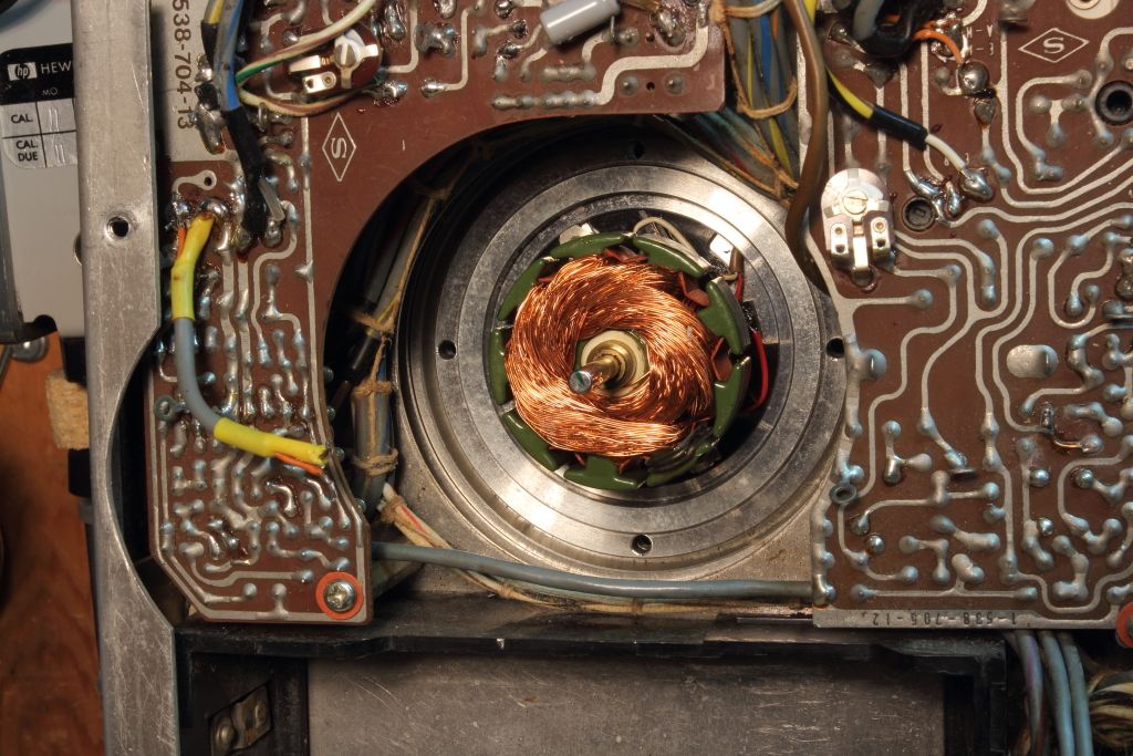
>>IMAGE<<
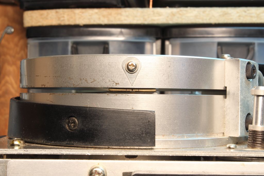
On the top side you have the video drum. Inside that is the head and a number of aligned components. The top half of the drum wasn't alignment critical and comes off with the removal of two hex bolts however anything attached to the shaft WAS. As the internals were carefully pulled away measurements were made to note component positioning and height relative to the bottom half of the drum. While mechanical tracking adjustments would take up any slack in realignment I simply could not afford to disturb anything that didn't need to be and said adjustments were often clearly marked with red locktite.
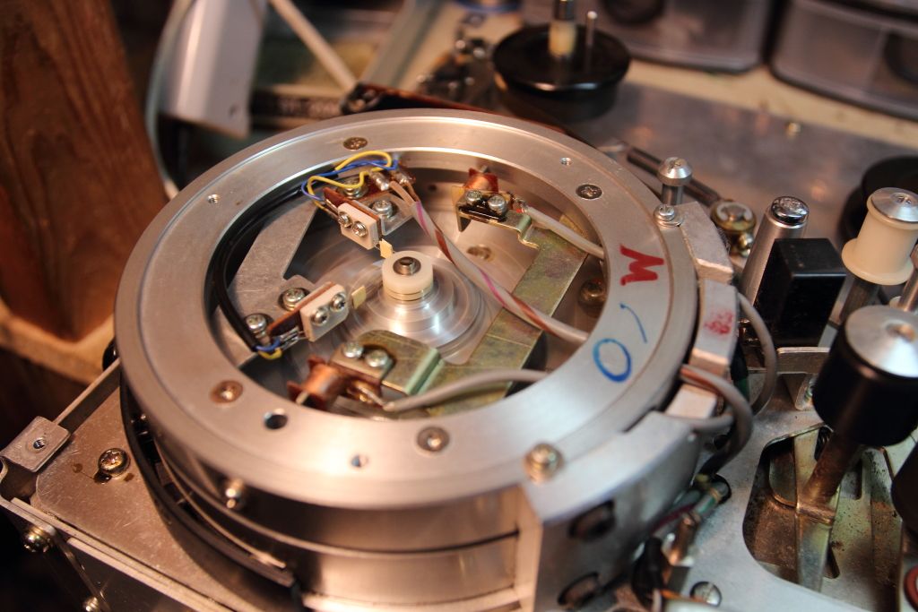
>>IMAGE<<
Once the head and the head mounting baseplate had been released I had access to the four screws that held he motor's permanent magnet in place. On the backside a soldering joint and cable was released so I could remove the bottom cover and pulley assembly and as the four screws came out my problem became extremely obvious.
>>IMAGE<<
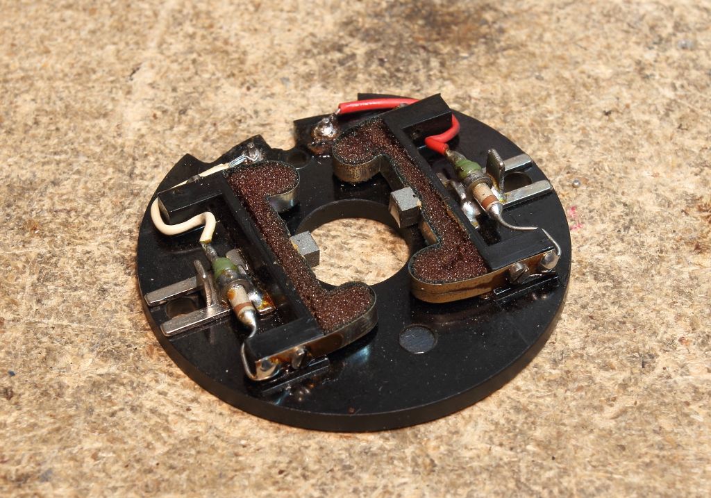
Now, there was a time when Japan's reputation for manufacturing electronics wasn't really.....the greatest. A lot of things that were coming out at the time were of okay-ish to poor quality. We already know that Sony had cut corners on this VTR to make it portable but this is not acceptable. Instead of proper metal spring-loaded brushes the brushes are held onto the commutator using two pieces of foam. As we have observed with the curiously similar looking brown foam found in an IBM PS/2 for example eventually this material breaks down and loses its ability to spring outwards when compressed. In this case as the foam died the brushes fouled up the commutator until no contact could be made. The green residue is also the chemicals in the foam leeching out and attacking the metal clip itself.
Now is a good time to bring up why this motor is so important. Aside from spinning the head it does....well, just about everything. The cabling we disconnected earlier to remove the permanent magnet body of the motor contains a winding which is used to generate a sync signal for the camera. No motor rotation meant not only could the camera not output any video signal but there was no sync signal to drive the camera's CRT viewfinder either. We aren't done yet either. The pulley on the end connected to the capstan and the take-up reel.
Forget the VTR, literally without the motor absolutely nothing would work. It had to be repaired.
I had to somehow replace the foam. Springs were one option however how to keep them in place was not looking promising. Glue would be messy. I could always replace the foam as more modern materials are less prone to this breakdown but it had to be of the proper density. Too stiff and either as the brushes wore down you would would eventually lose contact again or wear the brushes too quickly. Too soft and the contact would be too weak and in the jolting and vibration of carrying the unit around you would have signal drops associated with the motor failing to maintain a constant speed. I ran through a number of different materials until I stumbled on the pink antistatic foam I normally use to store spare boards for my larger Silicon Graphics machines.
>>IMAGE<<
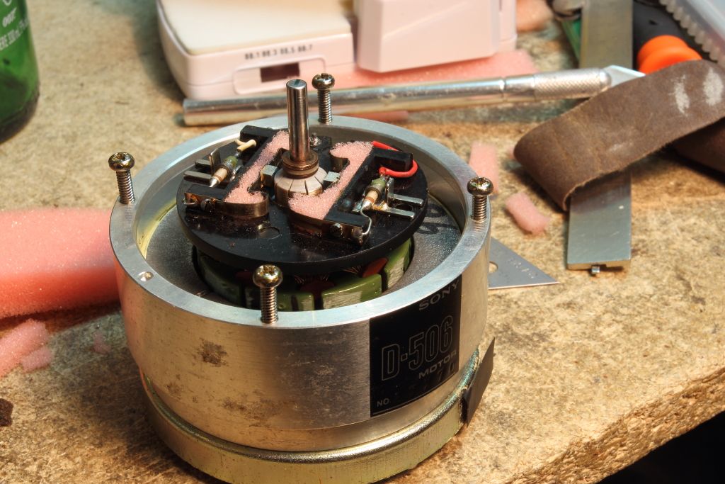
Cutting it into simple bracket ( [ ) shaped pieces slightly thicker than the decayed segments seemed to bring the brushes back into good contact with the commutator. A quick sanding and we were perfect. Now it was time to reinstall everything.
>>IMAGE<<
Worth pointing out that it's rather hard to retain brushes when you can't see them. It took a bit of effort with some tweezers to keep the brushes spread open so the motor could be assembled.
After everything was assembled and aligned an external power source was connected to the motor and the power slowly brought up. To my delight the head began to spin.
The external source was removed and the motor's cabling soldered back down. The deck was then setup with a regulated external source and the motor speed adjusted. The horizontal frequency had to be set to 15.75kHz which again is set using the motor. Because of the new foam pads the contact was so good that the motor was spinning slightly faster then it needed to be. This was also where I determined my HP 5221A counter wasn't going to be accurate enough so I switched to my HP 5334A counter to make the final speed adjustment.
>>IMAGE<<
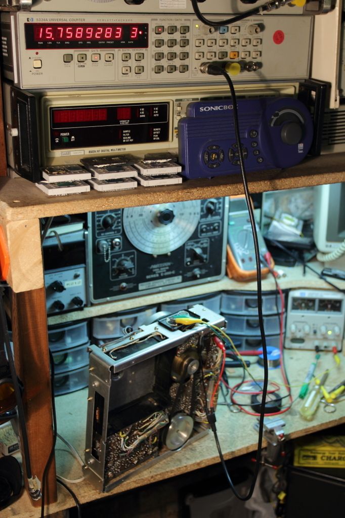
At this point all the necessary signals travelling around and out of the VTR were once again within range and we were ready to move onto the camera. While things should be working now, the camera still displays nothing on the viewfinder and the outcoing signal shows no change regardless of what you put in front of the lens. Obviously more investigation is needed but that's for another blog entry.
The VTR is record-only. You cannot play back anything. You also have no fast-forward or rewind. Attached inside the lid is a hand crank you slipped into holes on the spools and manually wound the tape. Its resolution was also not too impressive either. At seven Inches Per Second one reel of tape held approximately 20 minutes of footage with 220 horizontal lines of resolution. Literally you turned it on, pointed at your subject, pressed RECORD, then ran back to the tape machine at home to play it back.
About two months ago one of these kits came to my attention for a reasonable price. It wasn't apparently working but with the service manuals included I couldn't resist.
>>IMAGE<<
Indeed it wasn't the most mint condition artifacts but indeed it was rather complete. Cables, manuals, service documentation, AC supply, tapes and spools and even the little aluminum clip that holds the microphone was in the box. The only thing it didn't come with was the microphone, hand crank and the presumably now long dead lead acid batteries. Indeed however it did not work. A required 9v for running some of the logic was not being created and the drum was not spinning. The camera also had some issues but we'll get to that later. Without yet glancing at the schematics I assumed that the drum motor was brushless and some form of stepping action was required to bring it up to speed. After several hours of poking around it was discovered that the 9V regulation circuit was in fact two transistors and a potentiometer. While one transistor tested good, the other did not.
>>IMAGE<<
>>IMAGE<<
Simply put, these transistors are O L D. Sourcing a replacement can sometimes prove to be rather hard. While the DVK-2400 proudly stated it was an all-transistor design (41 transistors and 21 diodes, to be exact) it rarely used anything more than the 2SC401. This transistor has been out of production for a number of decades. In fact, even the substitutes have also been out of production for a while now. Thankfully because of how simple the circuit was the modern and extremely common 2N3904 made a perfect substitute. After some soldering and a careful voltage adjustment we had our 9V....but still no drum rotation.
At this point I began to better review the schematic and the exploded diagrams of the head assembly. Indeed there was something unexpected.
Both diagrams indicated that deep within the drum and the motor there was a set of brushes. While there was a simple biasing circuit used to get the motor up to speed after hunting down the cabling for the motor a simple resistance check found that the circuit was open. Great. Either the brushes had worn or a winding had opened. Regardless, getting in was not going to be fun.
>>IMAGE<<
On the top side you have the video drum. Inside that is the head and a number of aligned components. The top half of the drum wasn't alignment critical and comes off with the removal of two hex bolts however anything attached to the shaft WAS. As the internals were carefully pulled away measurements were made to note component positioning and height relative to the bottom half of the drum. While mechanical tracking adjustments would take up any slack in realignment I simply could not afford to disturb anything that didn't need to be and said adjustments were often clearly marked with red locktite.
>>IMAGE<<
Once the head and the head mounting baseplate had been released I had access to the four screws that held he motor's permanent magnet in place. On the backside a soldering joint and cable was released so I could remove the bottom cover and pulley assembly and as the four screws came out my problem became extremely obvious.
>>IMAGE<<
Now, there was a time when Japan's reputation for manufacturing electronics wasn't really.....the greatest. A lot of things that were coming out at the time were of okay-ish to poor quality. We already know that Sony had cut corners on this VTR to make it portable but this is not acceptable. Instead of proper metal spring-loaded brushes the brushes are held onto the commutator using two pieces of foam. As we have observed with the curiously similar looking brown foam found in an IBM PS/2 for example eventually this material breaks down and loses its ability to spring outwards when compressed. In this case as the foam died the brushes fouled up the commutator until no contact could be made. The green residue is also the chemicals in the foam leeching out and attacking the metal clip itself.
Now is a good time to bring up why this motor is so important. Aside from spinning the head it does....well, just about everything. The cabling we disconnected earlier to remove the permanent magnet body of the motor contains a winding which is used to generate a sync signal for the camera. No motor rotation meant not only could the camera not output any video signal but there was no sync signal to drive the camera's CRT viewfinder either. We aren't done yet either. The pulley on the end connected to the capstan and the take-up reel.
Forget the VTR, literally without the motor absolutely nothing would work. It had to be repaired.
I had to somehow replace the foam. Springs were one option however how to keep them in place was not looking promising. Glue would be messy. I could always replace the foam as more modern materials are less prone to this breakdown but it had to be of the proper density. Too stiff and either as the brushes wore down you would would eventually lose contact again or wear the brushes too quickly. Too soft and the contact would be too weak and in the jolting and vibration of carrying the unit around you would have signal drops associated with the motor failing to maintain a constant speed. I ran through a number of different materials until I stumbled on the pink antistatic foam I normally use to store spare boards for my larger Silicon Graphics machines.
>>IMAGE<<
Cutting it into simple bracket ( [ ) shaped pieces slightly thicker than the decayed segments seemed to bring the brushes back into good contact with the commutator. A quick sanding and we were perfect. Now it was time to reinstall everything.
>>IMAGE<<
Worth pointing out that it's rather hard to retain brushes when you can't see them. It took a bit of effort with some tweezers to keep the brushes spread open so the motor could be assembled.
After everything was assembled and aligned an external power source was connected to the motor and the power slowly brought up. To my delight the head began to spin.
The external source was removed and the motor's cabling soldered back down. The deck was then setup with a regulated external source and the motor speed adjusted. The horizontal frequency had to be set to 15.75kHz which again is set using the motor. Because of the new foam pads the contact was so good that the motor was spinning slightly faster then it needed to be. This was also where I determined my HP 5221A counter wasn't going to be accurate enough so I switched to my HP 5334A counter to make the final speed adjustment.
>>IMAGE<<
At this point all the necessary signals travelling around and out of the VTR were once again within range and we were ready to move onto the camera. While things should be working now, the camera still displays nothing on the viewfinder and the outcoing signal shows no change regardless of what you put in front of the lens. Obviously more investigation is needed but that's for another blog entry.