cj7hawk
Veteran Member
Hi All,
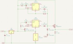
It's not my schematic - just a repackaging of one of the original Osborne1A's video adapter, but modified to fit in the very tight slot of the Osborne1Bs video/reset/battery bay.
It's a low-profile design and comes out roughly flush with the top of the face, so will pack away nicely. I wil make up a nice case for it so it looks good, and can be easily installed and removed. Due to the design, it only fits properly one way, so should also avoid those incidents of people plugging them in upside down. All of the components sit below are are pretty much touching the O1's surface, so it's very tight in there, and components are either folded flat or fully seated. The potentiometer for the horizontal sync width is seated fully in slots so that the adjustment can be accessed from the PCB side also, keeping it all out of the way.
The main change I made was to switch the sides of the chip swapped the horizontal timer for the vertical timer, mainly to make it all fit nicely.
Happy to share files if anyone is looking to make their own. It's entirely single-sided as you might guess from looking at the copper. ( I love the simplicity of a good single-sided digital design... )