• Please review our updated Terms and Rules here

Osborne Executive Blank Screen on Boot

jj_darling

New Member
Joined
Jul 25, 2012
Messages
4
Location
Olympia, WA
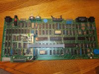
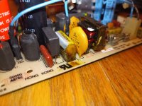
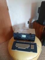
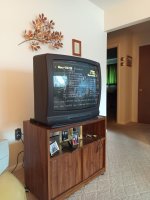
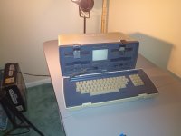
A few years ago a friend of mine gave me an Osborne Executive as a gift knowing that I was interested in vintage computers. It had belonged to his sister's in-laws, and he wasn't sure whether it ran or not. Upon powering it up I found that it ran (fans whirred, caps charged up, power light came on), but the screen never lit up. I was disappointed (always loved that amber glow), so I tried troubleshooting and trying to figure out how to make the thing go-- the external display jumper has been removed, cleaned, and replaced; the internals have been inspected for damage (none visible, at least not in terms of blown up components, missing/corroded connectors, etc); and I connected the composite video out to a TV and verified that the internals function properly (got the boot screen and was able to launch Zork from a disk, although the screen overscanned so much that I couldn't read the command prompt). As far as I can tell, there's nothing physically wrong with it, and I couldn't figure out how to test the display independently from the rest of the internals so I can't verify if it works.

Any tips on how I might proceed here? I can't wait to see the "East of house: There is a mailbox here." prompt on this thing!
 
Yes indeed. So that means the tube is good, right? So then it must be an issue in communicating data to the display. Or a calibration issue? Since the Executive can't do graphics does that mean this display is just a terminal display (like a teletype) that's being fed serial character data in stead of an analogue image signal that would need calibration?
 
It does mean the CRT is most likely okay, however there's a pile of circuitry on the display itself. Let's see what we can find out. The Executive uses a Zenith DT4 7" display (almost no manufacturers back then made their own displays, but rather purchased OEM kits). The schematic is here.

As you can see, there's not much to it. The usual culprits should be looked after; bad solder joints (the DT4 seems to have been afflicted with that ailment in particular). The schematic shows where to check voltages. Make sure that all connectors are fully inserted (they could get bounced loose). If you turn the brightness full up, can you see a faint raster on the screen? Since we know that the CPU section works fine, this breaks down to a basic B&W TV repair task.
 
I know this is a bit basic but have you checked the brightness/contrast controls on the front?
 
Okay cool, I'll have to find a multimeter and start looking around inside the CRT housing. And no, playing with the knobs has no visible effect on the screen. I've never used a schematic as reference for diagnosing circuitry problems before-- where should I start? Should I just be testing at the points in the circuit where the schematic shows a hexagon or circle with a voltage in it?

Thanks for the help!
 
Start by doing a visual inspection of the video board. Do you see any obviously damaged components? In other words, are there any charred resistors, bulging capacitors, etc? A sniff test can turn up some amazing things...

For now, don't bother to disconnect the anode (high voltage) lead from the CRT--although I doubt that there's still a charge on the tube, it can zap you if you're not careful.

Now flip the board to the solder side. Look carefully (use a magnifier if you have to) at all the solder joints--are there any that look questionable? A joint that was marginal when this was still a young box can go bad with age. Resolder any that look iffy.

Now, put everything back, reconnect the connector to the CPU board and power the thing up. If you still don't get video, carefully take some measurements where marked on the schematic. Stay away from the horizontal output section for now--that's anything that's connected to the flyback transformer, including the large horizontal output transistor.

Note that all voltages are measured with respect to chassis ground and that they're all DC, so make sure your meter is set to read DC volts. How do the voltages look?

While we're at it, is the multimeter the only piece of test equipment that you have right now?
 
The only pieces of test equipment I have right now are my five senses-- though I'm planning on picking up a multimeter sometime soon. Perhaps I can hope for a bad solder joint to fix everything, but I imagine this project is going to be disassembled on the table for a while. I'll perform the sniff test and visual inspection and see if that turns anything up.

Hah, I wish I could just do what the service manual says:
1. Screen remains blank.
REPLACE video monitor (sections 8.1.3 and 8.1.4).

If I did want/need a replacement at some point, do you have any suggestions on where to look for one? I imagine a quick googling isn't going to get me far in finding something like this.
 
Last edited:
ah, I wish I could just do what the service manual says:

If I did want/need a replacement at some point, do you have any suggestions on where to look for one? I imagine a quick googling isn't going to get me far in finding something like this.

An awful lot of OEM monochrome monitors had standardized connections. I suppose that you could look for a similar one--Ball Bros. (the Mason jar people) manufactured an awful lot of them, for example. But basically, it's the same with all of this old gear--try to repair what you can and hope that a replacement will come along.

Do you have any electronics-handy friends? A monitor isn't really the place to start because of the high voltages that can be involved.

Regardless, you can get some of the simple tools, such a multimeter locally. Radio Shack still sells soldering equipment and Harbor Freight offers a very inexpensive line of multimeters that will do just fine for your needs.
 
Hah, I wish I could just do what the service manual says:

If I did want/need a replacement at some point, do you have any suggestions on where to look for one? I imagine a quick googling isn't going to get me far in finding something like this.

I have a box of pieces and parts from a disassembled Osborne 1. This computer was "working" but had problems with the disk drives, so I sacrificed it to become my Osborne parts bin. I have a complete CRT assembly that may be useful. Also, with some guidance from others more knowledgeable than I am, perhaps some of the other components may also be useful. If you are interested (and if the parts are actually interchangeable), I would be glad to sell some pieces at reasonable cost plus shipping.

smp
 
Well, five senses are better than nothing. On the tube, there's the anode cap with a wire sticking out of it. It leads to the flyback. If you listen closely, do you hear a high-pitched whine at all ? (kinda like in an old tv)
Since the CRT heater is directly from 12V, it's perfectly possible to have a glow with a hosed horizontal section.
When you get your meter, check the +50V (+B) supply voltage.
If you're new to electronics, instead of getting a cheap DMM, see if you can't find an old-style analog multimeter (RatShack may even still sell them). The circuit-loading behaviour between DMM's and an analog (not a FET or VT meter) is different, and the readings on the analog should be easier to interpret.
Oh, and get test leads that you can clip to stuff. It's easier to not zap yourself if you're not trying to hold two probes and read the meter, all at the same time.
patscc
 
This thread is my life right now. I recently won an Osborne 1 in an online auction.
It arrived with a piece of masking tape on the case that read "beeped when turned on but nothing happened".
I got it to boot (I thought) by following the boot sequence I watched in youtube videos.
Then I found myself lucky enough to have an adapter to hook it to my tv.
Hooked up to my tv I could see it was actually booting and worked.
Why is my screen on my Osborne not working????
Before I could even consider the possibilities I heard the beautiful pop and fizz.
I unplugged it, cleared the smoke and a short time later had the capacitor yoinked off the power supply just like the guy on youtube told me to do.
Once put all back together I tested it to make sure everything was still good and it was except for the screen of course.
I have an Osborne OCC1 that appears to be from 1983.
It has the board for dual density disks or some shit but not the one for 80 line whatever the heck.
Sorry for my made up technical jargon. I'm new and dunno what to do.
I know the other guy had a different model Osborne (i think) but this is where duckduckgo brought me and it's the most hope I've got.
 

Attachments

  • signal-2023-12-08-203810_002.jpeg
    signal-2023-12-08-203810_002.jpeg
    595.1 KB · Views: 3
  • signal-2023-12-08-203810_003.jpeg
    signal-2023-12-08-203810_003.jpeg
    341.8 KB · Views: 3
  • signal-2023-12-08-203810_004.jpeg
    signal-2023-12-08-203810_004.jpeg
    252.5 KB · Views: 4
  • signal-2023-12-08-203810_005.jpeg
    signal-2023-12-08-203810_005.jpeg
    266.1 KB · Views: 4
  • signal-2023-12-08-203810_006.jpeg
    signal-2023-12-08-203810_006.jpeg
    205.5 KB · Views: 3
  • signal-2023-12-08-203810_007.jpeg
    signal-2023-12-08-203810_007.jpeg
    211.3 KB · Views: 3
I know the other guy had a different model Osborne (i think) but this is where duckduckgo brought me and it's the most hope I've got.

There's a lot of osborne 1 threads on this forum - have a look through the older ones, and download the Service Manual. You have a DSDD mod, but that's all. I'm assuming you have a composite adapter also if you can use your TV. Nice pic of the smoke. Glad you had the presence of mind to get a pic after powering it off :) I missed that opportunity.

So the PSU produces 12 and 5 volts. The screen gets 12v from the pin header IIRC. Make sure it's present. I've seen some with a bypass connector from the PSU also.

The pin header near the video jumper goes to the screen. Make sure it's on the right way. Make sure the bright/contrast pots are working. Make sure the signal is on the connector. Make sure the jumper block ( and NOT the composite block ) is installed. It carries the signals and often the power to the monitor via the pin header.

After that, just track the signal through the monitor via the schematics to see why the monitor isn't working. I haven't heard of many dead Osborne monitors yet, but there's always a first.

I see you have boot disks and everything else you need. The beep is normal. You can assemble the monitor / board / PSU all laid out on a bench to work on it, and you can use a different 5v 12v smps to power it for safety - :) 3A on each is more than enough, and be careful not to cook anything with shorts. Be careful of high voltages in the monitor too.

Good luck - :) Worst case, I think I saw someone in Canada on Ebay selling a replacement monitor module pretty cheap.. Would have bought it if the shipping wasn't a zillion dollars.
 
Back
Top