• Please review our updated Terms and Rules here

PC XT Power Supply Repair

neosunrise

Experienced Member
Joined
Jan 17, 2019
Messages
139
Location
Chicago, IL
So I recently got a PC XT power supply dirt cheap. The thing is in very good condition and the internal looks clean. But it didn't work. Initially, I plugged it in and flipped the red power switch but nothing happened. I made sure to hook it up to some hard drives, and a 286 motherboard. I connected my multimeter to the 12V port to monitor the voltage. As soon as flipped the switch, the meter needle (I used an analog one) moved just a tiny bit (perhaps for one needle width, in a 50V range) and then went back to zero. Fan did not kick in at all. I figured it could be capacitors because I saw one of the big caps bulged a little on the top. I ordered a full set of capacitors from Digikey with exactly the same specs, other than the smaller dimensions.

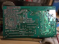
I did double check the polarity for each cap before I powered it on. Unfortunately, at the time I flipped the switch, the 3A fuse blew immediately. I replaced it with a 5A one (interestingly, the PCB says to use 5A, but the actual fuse was rated at 3A) and the same thing happened again. I do not want to waste my money by replacing more fuses. I measured the line filter cap which is not shorted. I also measured the diodes connected right to the line (mains) input and they seem to be good. What should I check next? Here are a few pictures of the PCB for you reference. Thanks in advance!
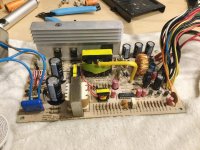
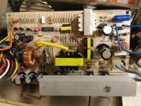
IMG_1894.jpg
IMG_1911.jpg
IMG_1912.jpg
 
There should be a inrush limiting power resistor and bypass relay somewhere, must be on the incoming power PCB. An issue there might be why it's popping fuses, assuming the fuse capacity and type is correct.
 
If the fuse blowup you have a problem in primary section. Do you check the diodes bridge and the big transistors from radiator? the capacitor seems to be in good position.
 
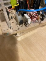
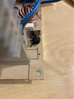
Thanks guys for your help! So this PS does have a thermistor on the input circuit. I took a couple of pictures for it. Its P/N is UEI005. How do I tell if it's bad?

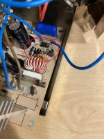
As far as the diodes bridge, I did not see a particular one piece unit but I would assume that the diodes marked by the red circle in the third picture form a bridge rectifier? I desoldered two of them and my multimeter measured fine - my way of measurement is very simple: test the resistance of the diode with red to negative and black to positive, and do it the other way around; one should give me very small resistance and they other should be very large. Can anybody tell me if this is a reliable test?

Additionally, what should I do to check the power transistors?

IMG_6186.JPG
IMG_6187.JPG
IMG_6188.JPG
 
Thanks guys for your help! So this PS does have a thermistor on the input circuit. I took a couple of pictures for it. Its P/N is UEI005. How do I tell if it's bad?

NTC thermistors decrease in resistance as they heat up. You can pull the thermistor out of the circuit and check its resistance as you heat the body of the thermistor up with a hair dryer. If the resistance doesn't change as you heat it up, or if it shows a dead short, then it's going to be bad.

As far as the diodes bridge, I did not see a particular one piece unit but I would assume that the diodes marked by the red circle in the third picture form a bridge rectifier? I desoldered two of them and my multimeter measured fine - my way of measurement is very simple: test the resistance of the diode with red to negative and black to positive, and do it the other way around; one should give me very small resistance and they other should be very large. Can anybody tell me if this is a reliable test?

That's an odd arrangement of diodes, but it appears to be the bridge rectifier. You need to use diode mode on your multimeter to test them, not ohms mode. You should measure around 0.5-0.6v of drop going forward and an open circuit when measuring it backwards. If you get weird readings, like a steady ramp of voltage going up, or a dead short both ways, the diode is bad and needs to be replaced. You may have to remove the diodes from the circuit to properly measure them.

Additionally, what should I do to check the power transistors?

Easiest way is to check it with diode mode. Depending if it's a PNP or NPN transistor, you'll have to test in specific polarity.

https://vetco.net/blog/test-a-transistor-with-a-multimeter/2017-05-04-12-25-37-07

If you get a dead short or weird values, try removing it from the board and test it again. If it still shows a short or weird values, it's bad and needs to be replaced.
 
Check transistors Q1 and Q2 to see if they are still ok. But is more good to take them out from PCB. Check and diodes and resistors around Q1 and Q2 it is possible to be gone. If you do not have diodes on your multimeter you can check on resistor scale. put the black tester on cathode and red one on anode you suppose to get nothing, if reverse the tester you need to get some resistance.
 
Thank you everyone for your valuable comments. My apologies for replying late. So just got some time and did some tests.

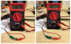
I first desoldered the diodes that form the bridge rectifier. Here are the results (all four have same results) - I would assume they are all good?
Diode.jpg

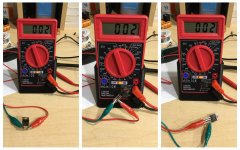
I then tested the two power transistors (C4242) screwed to the heat sink and both gave me exactly the same readings. No matter how I changed the polarity, the readings did not change at all. Can I assume that they both are shorted?
Transistor 1.jpg

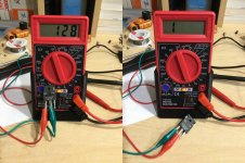
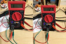
Last thing I did was to test the big transistor (SLP3040P) which is a combination of two diodes, as shown on the surface. And here are the readings - looks okay?
Transistor 2-1.jpg
Transistor 2-2.jpg

Any comments are highly appreciated!
 
Realize that almost any electronic component can measure ok, but yet fail under load (especially semiconductors).
 
Looks like you've found the problem.

Do you have a schematic?

I can’t find it on the Internet. It’s an ACG brand power supply which has almost no info available. Btw, can I use anything else as a replacement for c4242? Looks like they are no longer being sold in new condition, and even used ones are are not easy to come by.
 
I can’t find it on the Internet. It’s an ACG brand power supply which has almost no info available. Btw, can I use anything else as a replacement for c4242? Looks like they are no longer being sold in new condition, and even used ones are are not easy to come by.

Type C4242 equivalent and it comes up with lots of alternatives, but most are also obsolete. The C4242 is available on Ebay for not much though so even though they are from China, probably worth a punt as you can sense check them before fitting.
 
Cool. Thanks for the info! Will give those a try and see how it goes. I mean, repairing these old electronics is really not cheap. Already spent a good amount of money on the caps and now... Hopefully it will not be more expensive than a working used PS on eBay.

Happy New Year guys!
 
Here are a couple Schematics I found somewhere on the Internet. It has the same Transistors.

AT_compow11.gif
ATX_psu_schematic.pdf

Send me a PM with your email address and I'll send you an email with the *.gif file


Larry
 
Here are a couple Schematics I found somewhere on the Internet. It has the same Transistors.

AT_compow11.gif
ATX_psu_schematic.pdf

Send me a PM with your email address and I'll send you an email with the *.gif file


Larry

Thanks Larry for offering help! I replaced the two C4242s with J13007-2s and now the power supply works perfectly fine. I'm still curious why these failed.
 
Back
Top