• Please review our updated Terms and Rules here

PCW9512 - Brightness/Contrast Controls

Crashedfiesta

Experienced Member
Joined
Apr 16, 2022
Messages
82
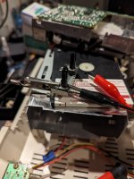
I've acquired a PCW9512 which works (or at least shows the expected white screen with no disk inserted - disks are on order). In the process of removing the cover it became obvious that someone has previously broken the contrast and brightness knobs so when I went to pull the plastic covers off they went all floppy.

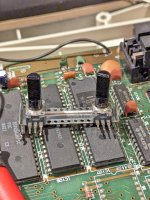
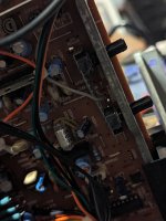
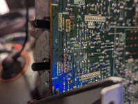
Opening it up fully, both variable resistors are broken but had been hot glued into place. Hmmm. I don't have a problem replacing them but not sure what values they should be. The service manual helpfully gives values for all of the variable resistors on the board, except these two. It describes them as a 'gang' but doesn't give the actual value of either.

On top of the first one is the number '104' and the other has '501'. So, could that mean 100k ohm and 500 ohm? Or am I barking up the wrong tree?
 
The term ganged with regard to a potentiometer means, to me, that two or more potentiometers are attached to a single shaft.

501 and 104 are coded values (in ohms) with the the first two values x 10 to the last value. So, 104 means 100 kOhms and 105 means 500 ohms - correct tree receiving barking.

There are other considerations ~ linear / logrithmic, number of turns and a bunch more.

Can you post a clear picture(s) - any manufacturing info would also be helpful as well as the dimensions.

e.g, https://www.tti.com/content/ttiinc/en/resources/blog/potentiometers.html
 
I just checked the 9256 service manual and they are in that one and I think that's supposed to be the same as the 9512 ( not 100% certain ) - They are listed as 10K for bright, and 1K for contrast.

So those numbers don't match up. And as was said, the code you are reading is correct, so I'd assume that's what has been installed in your chassis.
 
too late to edit "and 105 means 500 ohms" oops 501 means 500 ohms as you said. I was trying to use your example and transposed the numbers- 105 is actually 1,000,000 ohms.
 
If anyone is interested I solved this by supergluing the little metal plates to the front of the plastic carriers. Seems to work! :)

(I did finish the soldering after I took the last picture..)

I could've got the bigger value pot from eBay here in the UK (via a Chinese supplier) but I struggled to find the 500 ohm one so I hope this repair holds for a while.
 

Attachments

  • PXL_20231016_175803640.MP.jpg
    PXL_20231016_175803640.MP.jpg
    7 MB · Views: 3
  • PXL_20231016_180433636.MP.jpg
    PXL_20231016_180433636.MP.jpg
    6.3 MB · Views: 3
  • PXL_20231018_185918318.MP.jpg
    PXL_20231018_185918318.MP.jpg
    5.5 MB · Views: 3
  • PXL_20231018_190003493.MP.jpg
    PXL_20231018_190003493.MP.jpg
    5.6 MB · Views: 2
Yes it's working - or at least the CRT displays a white screen. I'm waiting to acquire a CP/M disk for it and I've replaced the drive belt already, so just need the disk. 🙂
 
Have you got a boot disk for your PCW yet?

If not, I should be able to help. I'm in the UK. I've got an image file for the 9512, and I think I've got all the necessary bits as well (incl a boot sector), but writing the image to real disk should be OK. I've got one of the uIDE drives, which I could fit onto a 8512 (rather than the usual 8256) so the image size will fit onto the source drive.

Not done this before, but it should work.

Geoff
 
I've not got a boot disk yet. I have an image but then realised I have no way to write it to a disk...

The drive in the 9512 is double sided with 80 tpi (I think) but the only other 3 inch drive I have that I could use with a Greaseweazle is single sided 40 tpi. Doh.

If you want to read about my escapades with this I updated my blog a week or so ago. 😁

 
Yes, the A: drive fpr the 9512 is the 80t 2 sided drive, as per the 8512 B: drive.

I know very little about the Greaseweazle system, but I understand that the GW needs an operating drive to connect to, so I guess that you would need one in the PCW to receive the (translated ?) data and one to work with GW to send it?

When I checked the files I have, I found some complications too, but these MAY have 'get-arounds'?

Yes, I have an image, which may be the same image you've got (?), this is of a later version of the 9512 system, BUT it's been processed as an 'Extended' image (I don't know why) and the software I have for writing images to disk cannot handle Extended images (although Joyce can read/Load the image fine, and the software for loading writing the image is also from John Elliott).

There MIGHT however be something for converting the Extended image to a normal CPC image.

Secondly, I have an earlier version of an 9512 boot disk, actual disk, BUT the actual disk is a 3.5" disk. This is an earlier version of the system, but should still be OK for you to boot your system, once you're booting then we can work from there. Prob I can Image the 3.5" disk, then write the image back to a 3" disk. The disks would appear identical?

Thirdly, I have an actual Loco boot disk (official) which I'd like to keep, this is of a very early 9512 system. It does NOT say it's for the 9512, it says it's for the ASF (Auto Sheet Feeder), but the files on the disk are compatible with being a boot disk for the 9512. I should be able to use DISKCOPY to make a copy, just got to be careful as to which version of DISKCOPY I use so I get the correct boot code. Or just use the longer method and image and then write the image?

There are tiny differences between the three system versions, these might not matter. Like I said above, get it working, THEN sort out any remaining issues?

Geoff
 
Back
Top