• Please review our updated Terms and Rules here

PDP-11/44 Restoration (part 2)

Old Computers

Veteran Member
Joined
Aug 30, 2012
Messages
510
Location
USA
After having put this project on a long hiatus I have finally decided to try and finish up my PDP-11/44 restoration.

So a quick recap of what was being done:

The system would initially not turn on. A capacitor was replaced on the Bias and Interface board, and then the system would power on. The system would work, but then the power light started to flash indicating that a voltage was out of tolerance. The +5V and +5VB were considered suspect at the time. I started to build a dummy load for the system, but never got it finished.

Here is the original thread describing what was done before: http://www.vcfed.org/forum/showthread.php?32576-PDP-11-44-Restoration


Now I have been debating a few different paths to take from here. 1) Shotgun replace all the capacitors in the PSU (especially the Bias and Interface board), 2) build the dummy load and observe the system under the test conditions some more, or 3) source a replacement PSU or PSU boards if possible. I am also thinking about buying a couple of extender boards to get better access to the voltages to measure at the backplane.

I did pick up an ESR meter and have tested some of the capacitors on the boards. They all seem to be okay judging from the table, but the table is somewhat hard to interpolate if the capacitor is not really close to the listed values. I also did a check with a plain capacitance meter. One capacitor on the memory regulator board read a higher capacitance out of tolerance, but that might just be a result of being an in-circuit test. I am keeping that one in mind just in case.


I also managed to pick up the PDP-11/44 maintenance card which I didn't have access to before. It actually has brief troubleshooting steps for the DC ON light flashing. A couple of things it mentions are that D25 may be installed backwards on the Console Interface Module or a battery backup jumper may be installed on the backplane. I doubt its either of these since the voltages have been checked before, but I thought it might be worthwhile to check just in case. I found D25 on the CIM, but have no way to simply tell if it is backwards because there is no indication the board. I could probably trace the schematics if needed. As for the battery jumper, I don't think it is installed because as far as I know this system never had a battery backup unit. I also don't know where to find this jumper on the backplane.

Thank you for any pointers you may have.
 
I would 2) build the dummy load and observe the system under the test conditions some more

>One capacitor on the memory regulator board read a higher capacitance out of tolerance
The tolerance on electrolytics can be as high as -2%/+80%. For a capacitor that is not part of a timing circuit or a tuned filter, bigger is usually better.
We have also seen that capacitors that are run at a voltage below the rated voltage usually have a capacitance on the high side of the tolerance.
 
I will go ahead and try to get the dummy load built soon. My only concern about the dummy load is how to hook it up to the +5v rails on the PSU. The backplane is connected to the PSU by these heavy "flex cables" but they really are more like copper sheets that connect to it via a screw in terminal.

There are a couple of other terminals that look like I could screw something into, but then I'm afraid of heating up the connection too much. If I build the dummy load like suggested in the previous thread, I would end up drawing about 50A. Another suggestion was trying it at just 25A too. Also what gauge of wire would work best for this? My previous test setup for 6A used heavy speaker and heavy alligator clips. I know the speaker wire probably couldn't tolerate that amperage, and especially alligator clips.
 
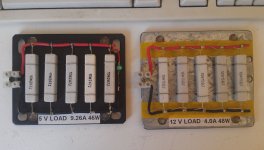
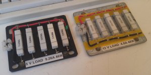
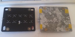
Here are the 5V and 12V PDP-11 dummy loads I built, I just copied Malcolm Macleod's ones he made for loading his 11/23 from his very useful website (original page, can't find the latest link to it):
https://web.archive.org/web/20160227030057/http://avitech.com.au/pdp-11-03/ba11nc/ba11nc.html

Mine have the ceramic resistors tie-wired down to a 3mm (1/8") metal plate for heat dissipation. The connectors are mains wiring 'chocolate block' terminal strips. Urethane feet keep the tie wiring from scratching surfaces.
I've put an indicator LED on the 5V load, haven't got around for one on the 12V yet.
PDP-11_dummy_loads_1.jpg PDP-11_dummy_loads_2.jpg PDP-11_dummy_loads_3.jpg
 
Thank you both for the ideas. I am going to give that website a read for sure.

This PSU can supply 120A on the +5V rail so I will target my dummy load for about 24A if 20% would be sufficient.
The +5V is the only thing specified in the manual that has a minimum current draw necessary. So I will probably forego building a load for the other lines. I also don't know of a good way to get to those lines besides the backplane. What do you think of that?
 
I hadn't thought of making a card for the dummy load.

That is a good point about being careful about the backplane pins.

Looking at the maintenance card I see that the PSU can provide +/-15V at 3A, 12V at 5A, -12V at 1A, and another +5V at 10A. Would this 2nd +5V be the +5VBB?
So 20% of each would be 0.6A, 1A, 0.2A, and 2A respectively.

The memory card is said to draw 4.8A on the +5V, 1A on the +12V, 50mA on the -12V, and 1.5A on the 2nd +5V rail. What I can't tell is if this is continuous current draw or peak draw. It seems like the pins could handle the 20% of the max output if that is continuous draw for one card. Would it just be safer to not do this and risk damaging the backplane? It also appears that the memory is the only card that uses the other voltages, but I don't know if the disk controller uses those too.


My configuration probably does draw at least 45A on the 5V line (not including the disk controller cards and a serial port card).
 
Thank you for that piece of information.

Do you all think it would be safe to just not load the other voltages if the mail 5V rail is the only one that needs a minimum current load? I don't want to burn out the backplane with too much current. I was thinking about buying an extender card or two so I could easily connect wires for the voltmeter.

I have gotten some parts to make the dummy load for the +5v rail. I will target it to draw about 24~25A. It has two 0.1 ohm 140W resistors. So each individual resistor would dissipate about 65W of energy. There are two brackets with screw holes open on the 5V rail on the PSU. I am going to try to connect the wires to those using a screw. Once I finish building it I will let you guys know.

According to EK-BA11A-TM-003_Aug83 the H7140 has a minimum draw of 6A on the +5.1 V supply and 0.0 on the rest. So you could reduce the load a bit, say 10~12A if you have the parts. Bolt the load to the PSU with short lengths of 12 gauge wire.

An extender card to aid measurement is a good method. Do not use it for the load device.

Heed the cautions on Page 2-9 in the manual. No rings, watches or contact with HV!
 
I will not use the extender card for the load device. I initially thought that I might do that, but it seems kind of risky. I wish there was an easier way to access the other voltages.

I will go ahead and order an extender card. I might even buy one without connectors so I could solder the test leads on to it directly and test it from there.

I actually went ahead and got 10 gauge wire just to be on the safe side. I could also add another resistor I have to make it draw 12.5A. In the first round of troubleshooting I did, one of the people giving me advice were suggesting that I draw closer to 50A. From my understanding that amount was to more closely approximate a fully populated system.

As for the warnings on the PSU, I will definitely heed them. When I obtained the machine I saw that warning and it made me uneasy working on the power supply at first. I am glad this PSU has all the fail-safes built in, but at the same time it seems to be way too complex. Too bad it's not a simple linear PSU.
 
A linear version would weigh about 5 times a switcher.

This is definitely a complex Switching PSU. A mid 1970's design, it had to deal with overvoltage shutdown, current overload monitoring, temperature monitoring, battery backup for memory, and control sequencing. It was built with discrete parts, op-amps, voltage regulators, TTL and 555 ic's. Hopefully the problems are minor, like faulty electrolytic capacitors. You should still be able to source replacement parts or equivalents.

Compare this to preceding generation, in which "transistors where used as fuses" in many of comments on the web!
 
Oh wow. That would be really heavy then! That thing already weighs about 50 pounds as it is. I have heard about the transistors as fuses comments. That is pretty interesting.

I am really hoping that the problem is something simple too. I am going to get the extender board ordered soon. I am in the process of building the dummy load and will give an update once it's ready.
 
That's definitely a good idea for the dummy load. I will keep that in mind for building the dummy load for the other voltages. Thank you!

I did manage to get the dummy load built for the +5V rail. I am still just trying to think of a good way to mount it on a board so it won't burn anything. I's about 0.2 ohms, and I calculated it will draw in the ballpark of 25 amps. Each resistor will dissipate about 64 watts of power (that's just above half of each resistor's rated power). Since the resistors aren't going to be dissipating their fully rated power, does that mean I probably won't have to worry about a time length for running those, or would it still be good to not run them for too long when testing the power supply?
 
I prefer to run resistors at no more than half their power rating, because they still get hot. But with the oil, it can obviously go higher.
At half the rating, I suppose they *should* be able to go continuously (with adequate convection cooling conditions). Add forced air cooling I would expect continuous operation to be no problem.
Then again, 15 minutes should be enough for most testing.
 
Back
Top