• Please review our updated Terms and Rules here

PSU help!!!! (Transistor identification)

...Maybe one component failed and then there was just a cascade of failures from that...

Not likely. A failed component might take out a couple more with it , tops...but a power surge (as Chuck (G) mentioned) would wreck havoc and take out a large number of them (such as you have)...
 
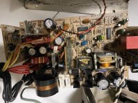
Hi all, a friend and I have been working or resurrecting a 5160 PSU (220v). It's been a mission!

We have replaces a number of components that were either obviously dead or corroded and crumbling.
Unfortunately, still no luck getting it to work.

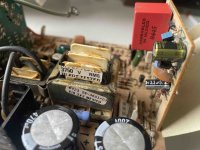
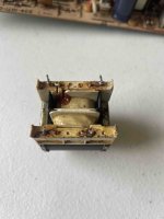
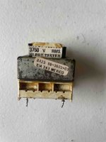
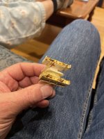
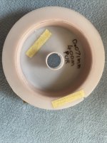
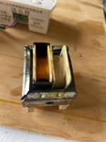
I was wondering if anyone recognises this part (see attached), and what would be a modern main switching transistors replacement.
The two on the board are dead, so I got some some J13007 transistors as we I thought they would work well...now it looks like these replacement transistors are not compatible as they do not switch on, even with the drive on the base looking ok.

Anyway, if anyone can help with identifying a modern replacement would be most appreciated.

Thanks

View attachment 1268107
For what its worth, and in case anyone else comes this way, I'm currently diagnosing what appears (from the photo at least) to be the exact same model PSU from a 5160. In place of the pictured component there are indeed MJE13007 transistors in place. (Q1, Q2)

If/when it's resurrected I'll report back with what had failed.

I'm using the opportunity to do a full electrolytics recap and will also post the cap list. The caps all look and test ok and there's no observable leakage but hey after close to 40yrs they're way outside their original design duty cycle.
 
Good job. Here's a little tip for fixing switching PSUs (also CRT monitors, amplifiers, etc.): put a light bulb (40W works great) in series with the mains power before powering the device up. This limits the current and prevents components from blowing up if there is a problem. Plus, if the bulb glows brightly when powering up the circuit, that tells you immediately that there's a short somewhere.
 
Seconding @bitwhacker here with the lightbulb idea, naturally the bulb needs to be of incadescent type, but a higher wattage is preferred - starting at some 100 watts. This is because some circuits such as PSUs or other capacitive loads might present an inrush current that cause the bulb to light up and subsequently cause a voltage drop large enough to cause erratic operation of whatever is connected in-series with the lightbulb. This is also to be noted with vacuum tube technology (think microwaves, CRTs, old radios, amplifiers) where, depending on the wattage and power consumption, all voltages of the circuit are dropped, including the filaments (not good).
But other than that, it's a good idea for testing purposes. An AC motor run capacitor of sufficient reactance can be substituted for the bulb, but it won't provide the "visual feedback" of the load :)
 
Last edited:
Thanks for the lightbulb tip. I did this and it behaved as expected with a bright glow on initial PSU power on then nothing. I also set up a load (50W globe) on the 5V output rail which is needed for a IBM 5160 PSU to start.

Perhaps this should be in a new thread - happy to start it if needed...

I've fault diagnosed further and the T5 transformer that provides "always on" 12V to the SG3524 controller chip has failed. The primary winding is open circuit. The T5 (as described in this document for a 5155 PSU but is the same for a 5160) takes 115VAC input and outputs 12VAC which is then rectified and smoothed before being used. Leg spacing is 1" between the primary pins, 3/4" between the secondary pins, and 1" between the primary/secondary pins. If anyone can point me in the right direction for a suitable replacement it would be much appreciated. I have no idea where to start :-(. Perhaps someone has an authentic original from an otherwise kaput PSU? (I'm in Australia)

I've added some photos of the problem component below.

After some searching I found this from a US stockist. Comments appreciated.
 

Attachments

  • IMG_7951.jpg
    IMG_7951.jpg
    381.4 KB · Views: 7
  • IMG_7957.jpg
    IMG_7957.jpg
    270.7 KB · Views: 7
  • IMG_7958.jpg
    IMG_7958.jpg
    272.1 KB · Views: 7
Last edited by a moderator:
Unfortunately I can't read your link, it says:

"Connection denied by Geolocation Setting.

Reason: Blocked country: Germany

The connection was denied because this country is blocked in the Geolocation settings."

Anyway, just about any small 110-120V to 12V transformer would work. For example, you could get something like this https://www.aliexpress.com/item/32833466889.html and find a way to mount it and connect it with some wires to the PCB.

The other options is to take apart the defective one, unwind the primary, counting the number of turns, and rewind it. I found that to take apart these lacquer dipped transformers, you can boil them in water for 10-20 minutes, which breaks down the lacquer a bit so you can take them apart.
 
Alex, thank you however the updated link displays a zener diode rather than the LG/Zenith 95-3601-03 transformer (ItemCode=ZEN95-3061-03). Seems like ued (from Illinois, US) are blocking connections from outside the US. Maybe something to do with export controls? My VPN allowed me to circumvent this but clearly not everyone can do it.

Bitwhacker, thanks for the useful pointers. I really like the idea of rewinding the primary as it retains more of the original machine. I watched some youtube videos and reckon I can build a winding jig to do this but it will be a longer term project. For now I will pop round to the local electronics store with your suggestion of any small 110-120V to 12V transformer. I understand a 240V to 24V will also work as the ratios are the same.
 
Ok, it's been a while but here's a good news update. I decided to rewind the primary winding of the T5 transformer rather than purchase something new. I built a winding jig, disassembled the core and unwound the existing wire. There were 3580 winds of 41 AWG wire. The gauge was determined by lightly sanding the coating and measuring 0.071mm diameter using a micrometer. I purchased 400m from Col's Metals and Copper Wire (CopperTech) on eBay with a PUR coating. Rewound the primary - the hardest part was getting the tension right with a good snug wind but not breaking the very thin wire. I used a small paintbrush to apply Elmotherm 009-0008 clear varnish to fix the wire every 1000 winds, and a some polyimide tape to protect the wire and improve the insulation once finished. For reference, the resistance of the primary winding now measured at 1040 ohms, the secondary is 14 ohms. Rebuilt the core and re-attached the original factory identification and "Hi-Pot tested" stickers.
I then soldered the transformer back onto the board. I used a 12V 50W globe as a test load and..YES!... the PSU started up for about a second each time before cutting out. I figured the output voltages were perhaps now out of range, what with the new caps and rewound transformer. I adjusted the R18 potentiometer which sets the output voltages and the PSU roared back into life. Woo hoo! My first foray into component level fault finding, diagnosis and repair is successful. So chuffed.
Pics:
T5-1 - the jig and the unwound birds nest
T5-2 - the transformer and the empty primary
T5-3 - the replacement wire
T5-4 - the rewound transformer
T5-5 - back in circuit, bottom right above the inrush caps
 

Attachments

  • T5-1.JPG
    T5-1.JPG
    1.3 MB · Views: 14
  • T5-2.JPG
    T5-2.JPG
    1.7 MB · Views: 15
  • T5-3.JPG
    T5-3.JPG
    895.2 KB · Views: 13
  • T5-4.JPG
    T5-4.JPG
    1 MB · Views: 13
  • T5-5.JPG
    T5-5.JPG
    511.8 KB · Views: 14
Wow, that is fantastic, @Jonno !

I am very impressed with your success in transformer rewinding. How long did it take? I'd guess that was a significant project.

And sorry about the link, I fixed it (again!).

- Alex
 
Hi @Alex, thanks for compliments and fixing the link.

The jig took about a day to plan, pull all the bits together and make. There are plenty of YouTube videos to choose from. I had to wait 3 weeks for the electronic counter from China. If I was to make it again I'd counterbalance the winding handle so it wouldn't swing by itself when left at the top of the cycle. The unwinding took about 2 hours. I had to be careful not to break the wire in such a way the loose end would be buried in the remaining windings. The rewinding took about 3 hours, plus drying time for each of the insulation varnishings. I had to be so careful not to break the wire - probably would have been better to buy 1000m rather than 400m and have the extra in case I had to start again. It's so cheap. Rebuilding the core was straight forward although I did deform one of the 'I's a little. Very happy to have kept as much of the original as possible.

As a follow-up, the original 10MB Seagate ST412 in the XT took about 20 restarts and at least an hour of runtime and a rest overnight before the read/write heads started to work again. The most recent file date I found on the drive is 1996 so the computer hadn't been used for 28 years. No wonder it was reluctant to give up it's secrets!

Do you think some of the T5 transformer specs may be of use to minuszerodegrees readers?

Cheers, Jonno.
 
Do you think some of the T5 transformer specs may be of use to minuszerodegrees readers?
This is the first that I have heard of T5 failing, and so right now, I consider the T5 failure as a one-off. If I hear of another T5 failure then I will probably note the multiple failures on my 5155/5160 PSU web pages, pointing the reader to this thread.
 
Back
Top