• Please review our updated Terms and Rules here

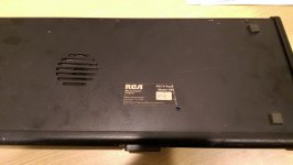
RCA VP-616 membrane Keyboard

jharre

Experienced Member
Joined
Jun 12, 2009
Messages
151
Location
Placitas, NM
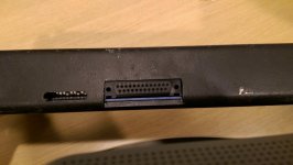
Does anyone have pinout information for the DB-25 connector on the back of these? The "manual" I found is pretty skimpy. It does say that it needs +5v and +/- 9-15v for the RS-232 connection, but not where to feed them on the connector. I believe they were produced in the early to mid 1980s.

<*> Jim
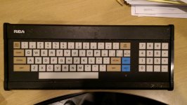
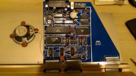
IMAG00141.jpgIMAG00142.jpgIMAG00144.jpg
 
Does it look anything like the schematic of the KB670 / KB675?

Yep, that's the "manual" I found. The schematic shows ground, +12 and -12 on the connector, but not +5. Guess that's tomorrow's project - tracing the +5v on the chips back to the connector.

Thanks for looking.
 
I checked my (unfortunately incomplete) keyboard but it is the smaller VP.623 version and it is parallel.. (it contains only CMOS chips)
But by following the tracks it should not be hard to find out which is gnd and which is +5 Volts assuming there are some recognizable chips on the board.
 
Yep, that's the "manual" I found. The schematic shows ground, +12 and -12 on the connector, but not +5. Guess that's tomorrow's project - tracing the +5v on the chips back to the connector.

Thanks for looking.

The KB670 / KB675 shows +5V on the DB-25 P4 connector pin 11, which is connected to the VIN pin 8 of U8 LP2951ACM 5V regulator. The VOUT pin 1 of U8 LP2951ACM is then the +5V supply for the rest of the circuit. If jumper W3 is installed then the U8 LP2951ACM regulator is effectively bypassed. If W3 is not installed then the +5V input on the DB-25 P4 connector pin 11 does not need to be a regulated +5V.

If your VP-616 version also has a LP2951ACM regulator then trace where its VIN pin 8 is connected and see if it is also connected to the DB-25 connector pin 11.

LP295x-N Series of Adjustable Micropower Voltage Regulators datasheet
http://www.ti.com/lit/ds/symlink/lp2951-n.pdf
 
That has an 8-pin CA3140 with the V- pin 4 connected to the -12V input and the V+ pin 7 connected to the +12V input. If your keyboard has the same part you could try tracing those pins back to the DB-25 connector.

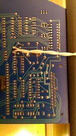
Yep, it does have a CA3140 and that's what I used to trace those pins back to the connector. -12v is on pin 17, +12v is on pin 18, and data out is on pin 2 of the DB25. There are significant differences between this board and the schematic. All the chips have the 'CD' or 'CA' prefix (old RCA numbers?) and there are no 74xx series chips on the board. However, the printed circuit board is a *very* pretty blue.

IMAG00147.jpgIMAG00149.jpg

Next step is to dig in the old parts box for a +5v, +12v, -12v power supply, plug it in - and stand back. :)
 
What is the 4-pin DIP part U12 in the upper left corner? Looks like it might be a bridge rectifier with the +/- markings. What is that connected to?
 
Back
Top