GearTechWolf
Experienced Member
I got these severed cord-ends from the trash at a recycling center based in a local homeless shelter.
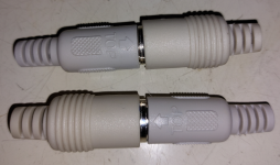
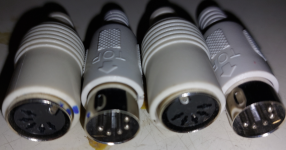
Today, I'm going to show you how I broke them down for direct re-use instead of just bodging wires onto the cut end of the cord, leaving a weak-point in the cord you build.
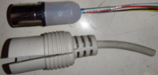
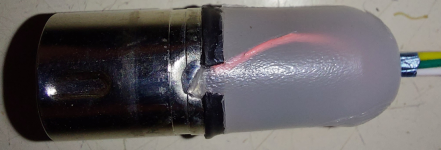
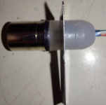
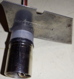
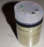
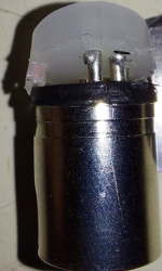
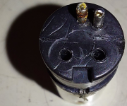
As you can see, I cut the outer sheathing along the mold-line on one side and peeled out the wires, potting, and plug from the core. (this does create a fair amount of waste, but now you can attach wires of larger size if needed!)

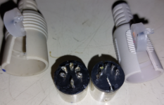
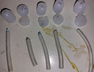
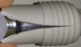
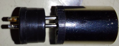
This next plug was the one from the cord of a Commodore power supply, it was molded in a slightly different way, as a singular piece instead of the two-part design above.
This required that I fully split it down the middle before I could take it fully apart.
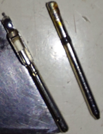
Another difference, is that the outer shield is not attached* to the central pin-holding piece (not even keyed to it!) and isn't electrically attached either.
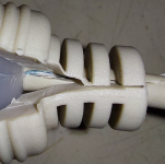
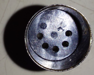
In the latter three pictures of this grouping you can see where I've started carving out excess plastic from the inside of the sheathing halves.
I did this to illustrate that even it could be reused with new or bigger wires if so desired. *(this was to my advantage and sparked the idea!)

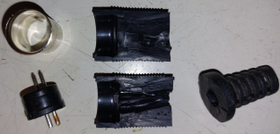
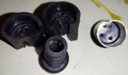
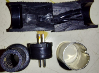
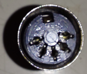
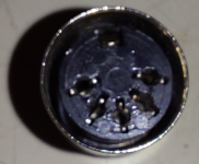
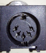
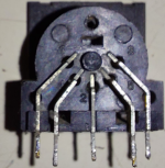
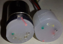
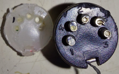
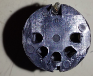
Here you can see that the DIN-5 plug has mold-marks that could make it a DIN-7 or DIN-8 if they were drilled out and populated, which is exactly what I did to make a full 7-pin power-plug.
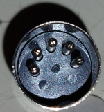
Part 1/3


Today, I'm going to show you how I broke them down for direct re-use instead of just bodging wires onto the cut end of the cord, leaving a weak-point in the cord you build.
As you can see, I cut the outer sheathing along the mold-line on one side and peeled out the wires, potting, and plug from the core. (this does create a fair amount of waste, but now you can attach wires of larger size if needed!)


This next plug was the one from the cord of a Commodore power supply, it was molded in a slightly different way, as a singular piece instead of the two-part design above.
This required that I fully split it down the middle before I could take it fully apart.
Another difference, is that the outer shield is not attached* to the central pin-holding piece (not even keyed to it!) and isn't electrically attached either.
In the latter three pictures of this grouping you can see where I've started carving out excess plastic from the inside of the sheathing halves.
I did this to illustrate that even it could be reused with new or bigger wires if so desired. *(this was to my advantage and sparked the idea!)


Here you can see that the DIN-5 plug has mold-marks that could make it a DIN-7 or DIN-8 if they were drilled out and populated, which is exactly what I did to make a full 7-pin power-plug.

Part 1/3
Last edited:

