• Please review our updated Terms and Rules here

Removed reset button

HansTRS

Member
Joined
Sep 9, 2023
Messages
18
Location
The Netherlands
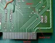
Recently I purchased a TRS-80 Model 1 and to my surprise the reset button was removed. A track was cut on the PCB and two traces to the connector were connected as shown in the photo.

I want to solder a new reset button, but I was wondering whether I should also repair the cut trace and remove the connection that was made.

Can anyone tell me what to do?
RESET.png
 
Hi Hans,

The trace cut and join may not be related to the reset switch being removed.

The trace cut/bridge mod removes +5V from pin 39, and changes it to GND. (Like the Japanese Model 1).
Will stop it running with small expansions which draw 5V from the motherboard.

A Momentary switch between the Centre-Left Pad, and the Top-Left Pad will suffice for a reset button.
(May need to check the through-hole plating hasn't been damaged)

Regards,
Leslie
 
Thanks Leslie. Judging by the solder, the reset button has recently been removed. The other soldering is more oxidized so it could have already been done during production. Now waiting for an ordered push button, I will let you know here what happens after I have installed it.

Do you think I can simply connect the Expansion Interface, despite the adjustments on the PCB?
 
Hans,

What kind of Expansion Interface do you have?

The earlier, buffered cable units have 5V on Pin #39, don't plug one of those in!

The later, re-designed EI boards have pin 39 as NC (Not Connected), so you should be ok with one of those.

Regards,
Leslie
 
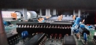
You can tell which EI you have by the orientation of the RAM chips inside. The early EI has RAM chips arranged front to back, while the newer version has them arranged side to side. You should be able to peek inside one of the port openings.
 
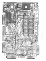
It looks like you are looking into a side port. Perhaps this image will help. Image is newer EI boardExpansion_Interface_Redesigned_PCB_Service_Manual_19xx_Radio_Shack.jpg
 
Back
Top