• Please review our updated Terms and Rules here

Reproduction Osborne 1 DD upgrade card

NRoach44

Member
Joined
Jun 19, 2022
Messages
37
Location
Perth, Western Australia
I've just obtained an OCC1 myself, but it's completely vanilla, with a 1.3 version ROM and no upgrades. Since I found the schematics for the upgrade in the Service manual for the computer I figured I'd challenge myself to reproduce it in KiCad.

I'm pretty confident I've reproduced what I can, but I would greatly appreciate any feedback, technical or otherwise, before I go and drop $90 on three boards that may or may not work!

I've put what I've got so far into gitlab, here: https://gitlab.com/NRoach44/occ1-dd-upgrade

My plan so far is to make a *electrically* accurate reproduction, and then once I'm happy with that, make one with a PC style pin header for Goteks.

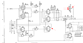
The original schematics are page # 98 and 99 of https://util.nroach44.id.au/misc/occ1-dd/2F00040-00_Service2ndEdition_1983_DDSchematics.pdf
I've PDF'd the rework's schematics here: https://util.nroach44.id.au/misc/occ1-dd/occ1-dd-remaster-20220706.pdf
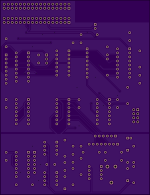
Finally, I have renders from OSHPark of the board:
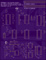
pcb_top.png
pcb_under.png

I've made the board a bit more cramped to save on cost, currently it looks to be about $30 USD each, before components.

Any feedback welcome!
 
The "page2" part of the schematic is empty. Is this intentional?
Semi-intentional - when I move the stuff that /should/ be in there to that page2 it suffixes the net names (/GND1 -> /page2/GNDA), which means that they are no longer connected between pages when I go to draw the PCB. For the moment that stuff is just outside the border of the main page on the bottom.
 
Where are you with this project? I'd be interested in buying one. I only have SS today :).
At this stage, I have touched up a couple of mistakes in resistor values, sent the boards off for production, and are waiting for them to arrive. Next steps will be ordering the components, assembling and then testing.
Still got a while to go before I'd call it "functional" but it's coming along.
 
This is a cool project. I have a SS-SD Osborne 1 and an upgrade (even with a gotek) would be really usefull.

Also, the screenpac schematics are in that technical document, which would be very interesting to have aswell. Especially the composite output.
 
This is a cool project. I have a SS-SD Osborne 1 and an upgrade (even with a gotek) would be really usefull.

Also, the screenpac schematics are in that technical document, which would be very interesting to have aswell. Especially the composite output.
ScreenPac looks to be much more complex than the SSDD card, but not ruling it out!

I happen to have a dumb little plug in module that sits on that video edge connector and gives composite out, so that's on my list to reproduce too.

That and a Drive C.

Once I have confidence that the board works I'll upload all of the details, and probably sell some boards at cost price.
 
I happen to have a dumb little plug in module that sits on that video edge connector and gives composite out, so that's on my list to reproduce too.
That would be really cool.

That and a Drive C.
I've seen something called a drive C on ebay once, it had little info on what it was. Is that some form of harddrive?
 
This DD upgrade card sounds like a great project to have available! Fortunately my Osborne 1A came with the DD card, but another one I had didn't have the DD card.

Drive C was a RAM disk AFAIK -- 192KB and 384KB options it looks like.
 
Okay, boards have arrived, I've put them mostly together, but I wasn't able to source U2 (7438) and U3 (74LS166) locally. I was able to swap the 7438 for a 74LS01 with some minor tweaks, and was going to swap the 74LS166 for a 74HC165, but the latter means a **lot** of annoying soldering. I've just ordered 74LS166 online and should get them in a week or so. I will probably swap these out on the next revision of the boards, just so that I can get everything at the one store.

I've still got to finish converting discrete resistors into the resistor networks, source a couple of passives I missed when ordering, and also make an PROM adapter so I can upgrade the system ROM.

Coming together OK so far!
 
I've built a ROM adapter that allows me to use the 27C256 as a 2732 ROM, and switch between the original 1.3 and the latest 1.44 on it, and that all seems to be working fine!

Today I connected up the finished board up to the motherboard, and it's in the really annoying segment called "almost working". I can see that data is being sent to the controller, and when the system is toggling the DDEN line, the RDCLK is halving / doubling to suit, but I don't actually know for certain what the frequency is actually meant to be! The variable resistor sets it, and goes from about 100KHz to ~240KHz. I've tried 200, 225 to no avail, along with slowly increasing it while the computer tries to boot.
The only other thing that I can think of is I had to substitute "CR3", a 1N5238 8.7V Zener diode, with a 5.1V + 3.6V combination. It puts out 8.2V or 8.0V under load, but if I shove 8.7V in there it doesn't seem to help.

I'm going to come back to it in a few days after a bit of time to think, but open to any ideas / feedback! I'll go get some oscilloscope screenshots later too.

It also doesn't help that I didn't calibrate the drive speed, so I probably should try that too.
 
After a bit of double checking, I was given a 20K trimpot instead of 10K! I'll update once I have a 10K installed and tested.

Looks like that trimmer is used to calibrate RDCLK, and I should be able to adjust it to the 125KHz/250KHz to match the signal from the drives.

Drive A came out to 202 RPM, which is ever so slightly out of spec (200+- 1 RPM), but at this point I'm going to leave it until I have the trimmer ruled out.
 
Very cool, especially the idea to make one for Gotek specific conversions. Not sure if you have ever used any of the Chinese PCB fabs, but someone like JLCPCB is going be significantly cheaper than OSHPark for a board of this size. I exported some gerbers from your repo and the per board cost for qty 10 is only $1.30.
 
Right, I thought I posted an update but I must have missed pressing post.

I ordered these from JLCPCB, which seemed to be the cheapest of the lot by a reasonable margin, and quality is perfectly sufficient for this stuff. Pretty happy all around.

I've replaced the pot with a 10K, but still can't get the frequency up to 125KHz / 250KHz. I wasn't sure it was going to help since I was running the pot fully short anyway.
I put another resistor in parallel with R12, to halve the resistance and increase the voltage going into and out of the pot, but the frequency still isn't quite there.
I also found I wired up RN4 wrong (since I couldn't get resistor networks, I just made them from resistors. In this case, I had it wired up all to one, where as this is just 4 resistors in a pack). I fixed it, to no avail.
I've wired up the board such that the RDCLK is still coming from the main board, but RDData is coming from the upgrade board, and SD disks read fine like this.
I wrote a new set of SD and one DD disk, just to double check, but they behave the same.

If anyone feels up to it, I'd be keen to see some measurements from an existing board - Oscilloscope would be handy, but just to start with I'd like to know the resistance that the pot is set to, and the voltage on all three pins of it.

The best solution for me would be to have another known good board to step by step compare it to, but I wouldn't be happy borrowing and shipping it back and forth. If anyone has a spare though, let me know!
 
How did you go with this? I just got an Osborne with this card installed, and have been working on repairing the Osborne - If there's any details from the card you need ( Pictures / Measurements ) let me know and I'll try to get some. I have oscilloscopes and logic analyzers available. I might have to bench the board as I'm getting a lot of failed tantalums on it, and my Drive A: smoked up on running, so there's a good chance I'll have to bench test some elements in the coming months. If I know what you need recorded I can probably put the LA or scope on it and get some readings at the same time.
 
How did you go with this? I just got an Osborne with this card installed, and have been working on repairing the Osborne - If there's any details from the card you need ( Pictures / Measurements ) let me know and I'll try to get some. I have oscilloscopes and logic analyzers available. I might have to bench the board as I'm getting a lot of failed tantalums on it, and my Drive A: smoked up on running, so there's a good chance I'll have to bench test some elements in the coming months. If I know what you need recorded I can probably put the LA or scope on it and get some readings at the same time.
Perfect!
I have ""full"" schematics, but I don't know what that trimmer / variable resistor's value is. Can you please measure the resistance between all three pins (should sum to 10K) and what the voltages are to ground on all three pins?
Secondly, can you measure the frequency of RDCLK on the upgrade board (U6/5 or pin 3 on the small header) - I *think* it's supposed to be 125 KHz or 250 KHz, based on DDEN, but I've never been able to push it up to that frequency.
`
Oh, I also suppose can you see if U6/13 connects to U1/11? It's "crossed out" here, but I can't say for certain if these schematics are correct.
Screenshot from 2023-02-11 18-07-15.png
 
Across the pot 5.84K to 5.85K, but by the same token, I measure 3.8K across the 4.7K resistor that connects the pot to 5v and 327ohms across the one to ground.

From the ground side to the wiper, 2.23K ohm and from the 5v side, 5.40K

Pin5 of u6 has continuity to Pin3 on the 9pin header. A visual inspection of the trace shows it does not go anywhere else.

I have two manual corrections on my PCB also from Pin3 of U4, however these appear to go as per the diagram you supplied, so if you see modifications on board photographs there, then they are to make the schematic correct.

I'm waiting on some PSU parts to rebuild my PSU and can get your voltages measured then.

Regards
David.
 
Back
Top