• Please review our updated Terms and Rules here

Resurrecting Toshiba T1000

ddoxey

New Member
Joined
Jun 21, 2022
Messages
2
Location
San Diego, CA
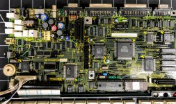
I'm working on reviving my Toshiba T1000.
I replaced all of the large Electrolytic caps and installed a new 4.8v 1400ma battery.

IMG_2304.jpg

The battery appears to charge normally.
When I power it on, the 5v rail spikes to 7v and then it shuts down. It is the same with and without the external power connected.

Speculating ... it seems like the power supply is not correctly regulated at 5v and there is an over-voltage protection kicking in.

Any thoughts?
 
Welcome to the forum, @ddoxey !

I'm sure that there are other folks here with T1000s that can offer suggestions. Since the battery is 4.8V theoretical, there is obviously a step-up circuit, and it seems likely to me that it isn't functioning correctly. You could find the output from the step-up circuit, and attach a regulated 5V supply there, of course without the battery installed, and see if the machine comes up that way.

- Alex
 
Per [here], the battery pack (disconnected) can reach as high as 5.2V

Page 2-7 of the maintenance manual for the T1000 (at [here]) indicates that with the battery pack fitted, and the AC adapter powered on, that the voltage at connector PJ10 (for battery pack) can range between 4.8V and 5.5V. (I note that voltage range will be fine for TTL chips). Are you seeing that, or is connector PJ10 where you are measuring the "5v rail" ?
 
Voltage at PJ10 measures 5.47V. Measured at the VDD pin of the ROM chip, voltage spikes from 0V to 7V, and then back to 0V in about one second or less.
 
I'm also currently working on a T1000 but have a different problem (no worries, I'm not going to hijack this thread).
I'll try to explain a bit on how this PSU works, though I don't think I completely understand it all yet.
In researching and tracing the power supply section I have found that the +5V rail is not actively regulated. It is solely dependant on the presence of the battery clamping the voltage from the 9V powerbrick down to the 4.8 - 5.5V modem7 stated above.

The power from the brick is fed through the large resistors on the top left to limit the current.
Depending on the amount of current required by the system. Some resistors are switched in and out of series based on floppy drive access, modem presense and on/off switch position. These resistors are switched in and out by Q24, Q37 and Q100.

The +5V rail is switched by the 3 MOSFETs grouped together just above R504 (blue 22 Ohm resistor).
These are P-Channel MOSFETs and require the -9V rail to be present to stay on. The whole thing is bootstrapped by Q39 and an SMD transistor (a 2SC3392 marked "AY6") connected to R515/R518 on the bottom of the PCB.

The other power rails for the machine are -22V for the LCD contrast bias and +9V / -9V for RS232/modem.
The -22V and -9V are generated by IC54, which is a TL1451 dual PWM controller which controls two inverting buck/boost topology DC-DC converters.
The +9V is generated using the oscillator from IC54 and a comparator (on of the two in IC30). This is similar to what is happening inside the TL1451, I'm guessing this is a costcutting measure. Later models like the T1200 all use two TL1451's or custom ASICs/Microprocessors.

All three higher supply rails are DC-DC type converters with voltage feedback.

I drew up a schematic of the PSU section which I haven't completely finished nor validated yet, once I'm confident it is correct (and legible) I will post it to my GitHub.

Long story short, the +5V rail jumping up to +7V seems to me as either a short to the +9V rail somewhere or maybe the battery disconnecting on powerup (unlikely seeing how it's wired in).
I would measure the voltages at IC54 (pin 8 is ground, pin 9 is VCC/+5V) and the voltages across C120 (should be +9V) and see wether they make sense.
If you need any more info, let me know. I'd be happy to explain/help further.

Edit: Looking at your picture more thoroughly, is that blue-ish stuff on the tab of Q22 corrosion?
If so, that may be (one of the) problem(s). Q22 is the main switch for the -9V buck/boost converter. Corrosion could have crept in to the package which can damage the transistor.
 
Last edited:
I'm also currently working on a T1000 but have a different problem (no worries, I'm not going to hijack this thread).
I'll try to explain a bit on how this PSU works, though I don't think I completely understand it all yet.
In researching and tracing the power supply section I have found that the +5V rail is not actively regulated. It is solely dependant on the presence of the battery clamping the voltage from the 9V powerbrick down to the 4.8 - 5.5V modem7 stated above.

The power from the brick is fed through the large resistors on the top left to limit the current.
Depending on the amount of current required by the system. Some resistors are switched in and out of series based on floppy drive access, modem presense and on/off switch position. These resistors are switched in and out by Q24, Q37 and Q100.

The +5V rail is switched by the 3 MOSFETs grouped together just above R504 (blue 22 Ohm resistor).
These are P-Channel MOSFETs and require the -9V rail to be present to stay on. The whole thing is bootstrapped by Q39 and an SMD transistor (a 2SC3392 marked "AY6") connected to R515/R518 on the bottom of the PCB.

The other power rails for the machine are -22V for the LCD contrast bias and +9V / -9V for RS232/modem.
The -22V and -9V are generated by IC54, which is a TL1451 dual PWM controller which controls two inverting buck/boost topology DC-DC converters.
The +9V is generated using the oscillator from IC54 and a comparator (on of the two in IC30). This is similar to what is happening inside the TL1451, I'm guessing this is a costcutting measure. Later models like the T1200 all use two TL1451's or custom ASICs/Microprocessors.

All three higher supply rails are DC-DC type converters with voltage feedback.

I drew up a schematic of the PSU section which I haven't completely finished nor validated yet, once I'm confident it is correct (and legible) I will post it to my GitHub.

Long story short, the +5V rail jumping up to +7V seems to me as either a short to the +9V rail somewhere or maybe the battery disconnecting on powerup (unlikely seeing how it's wired in).
I would measure the voltages at IC54 (pin 8 is ground, pin 9 is VCC/+5V) and the voltages across C120 (should be +9V) and see wether they make sense.
If you need any more info, let me know. I'd be happy to explain/help further.

Edit: Looking at your picture more thoroughly, is that blue-ish stuff on the tab of Q22 corrosion?
If so, that may be (one of the) problem(s). Q22 is the main switch for the -9V buck/boost converter. Corrosion could have crept in to the package which can damage the transistor.
Hi Fust,
this is great info! I am working to get a T1000 going, and have been following the schematic from a T1100 Plus thinking that they won't be identical, but there seem to be a fair number of similarities WRT component selections, etc. that it might be of use, but I've hit a wall. For me, I made a new battery pack, and recapped the main electrolytics, but all the unit has done (and continues to do) when I flip the power switch on is to flash the power LED red then green for a second or two, then the LED, Vcc and the other power rails switch off. Looks like the T1000 implements the switching of +5V Vcc as you described using the MOSFETs where the T1100 does not do that instead just relying on the power switch. I wasn't yet able to find what was switching the power, but thanks to your insights, I'm going to go have a look at this again.

While I was here, I thought I'd take the opportunity to ask if you have that schematic available anywhere, regardless of what state it's in?
 
Back
Top