• Please review our updated Terms and Rules here

Searching for IBM S/23 Datamaster users

Does anyone have a dump of the ROMs? In my (non-existent) free time I’d like to take a stab at disassembling them.
 
Does anyone have a dump of the ROMs? In my (non-existent) free time I’d like to take a stab at disassembling them.
There are available on line https://bitsavers.org/pdf/ibm/system23/firmware/
But you will have to manually load them into your disassembler.
If you looking for a predone image files of the ROMS images that you can just point the disassembler to and go. I don't know if any body will upload them here for you to short cut a flew steps.
 
Actually I made those dumps, they include the keyboard controller and if I recall correctly also the character generator.
I started using GHidra but if you use another disassembler I could try to learn how to use it. As our progress with the AS/400 is stalled until a new PC board or some tape drives arrive home, I propose to disassemble together if you wanted to.

EDIT
As a side-note, I have updated the article. It is still a WIP but it's taking form. I will also create some kicad symbols to deal with the connectors.
 
Last edited:
Hello, figured I'd drop a line in here and announce that I just acquired a Datamaster right before VCF Southwest last weekend. It came with all the yellow binders and both the big black binders, plus some additional books about its accounting software.

I've begun taking it apart to check for RIFAs, inspect the PSU, and check all the electrolytics. Thus far, the machine looks very clean. I'm having a bit of difficulty pulling the PSU out far enough to get to all the fuses, but would be interested in adapting another known good PSU since apparently it's easy (though I'm not aware that any of my loose XT or modern PSUs produce +24V).

I'll probably see you all more on the Discord side, but here I am on VCFed too (same handle).
Hello and welcome,

What's your model and configuration?

To make tests I can help you adapting an ATX to power it in a bench. If you have experience prototyping hardware, you could build a composite video adapter.
In a bench you wouldn't need the floppies but the controller must be present if you want to reach BASIC, but if you want to be stuck in the test screen it's safe to test without it. A memory board must also be present at the "base" socket when booting, otherwise you will have a black screen.
Check the capacitors in the memory boards, they tend to fail... result is black screen.
If you had a black screen nevertheless build a probe like this one: https://bitspassats.com/mediawiki/index.php/IBM_System/23_Datamaster_Resources
In case memories 02-09 fail I have a working patch; for the rest I'm still working on it. I hope you don't need those though.

Regards
 
Hey ggs,
Just started using this website again. ;-)

Just to introduce myself to this group. My first job out of college was for IBM in Boca Raton, FL. The first project I worked on was writing some (a lot actually) of the ROM code for S/23. It was released much later than what IBM wanted because of changing requirements. It was originally supposed to be compatible with the 5110 BASIC but was decided instead to be compatible to S/34 (the delay caused the release of the 5120 which is not much more than a 5110 repackaged in S/23 "skins"). That change of requirements resulted in a "slip" of a year in the release of S/23.

Development on the S/23 was arduous because we had no real infrastructure for building for the 8085 with an EBCDIC character set. :-( For much of the project a complete build took 2 weeks. Someone eventually wrote a cross assembler and linker that ran on the mainframe (S/370) and builds went down to 24 hours but that was fairly late in the project. But before then we were doing "patches" to the ROM code (early systems didn't have much in the way of ROM code...just enough to load a full image into ROM emulator cards...e.g. special RAM cards). Even though all of the code was in RAM, we still had to do patches. Usually we have 30-40 patches that needed to be applied to a build in order to continue testing/development. It was "fun" when a new build came out because we had to see if our previous patches had been incorporated properly into the new build (and of course there were always patches that were developed after the build was submitted and those had to be re-worked for the new build).

A lot of S/23 folks went on to develop the IBM PC. Dr Dave Bradley (inventor of Control-ALT-Delete) had his office across the hall from mine. ;-)
Great to have you here! It’s not often you get to hear from someone who was actually involved in bringing the machine to life (I often wish we could get a hold of specific people from the IBM PC team, but that’s a whole other story).

I wonder whether you might have some insight about the display side of things - specifically, about the character generation mystery I described at https://forum.vcfed.org/index.php?t...ter-display-and-character-generation.1247762/?
(Cliff notes/tl;dr version: the character ROM is laid out quite differently from the EBCDIC charset, and several characters from the latter do not appear to be present in the ROM at all. Those are mostly diacritics and “partial” glyphs - in principle they could be generated by picking apart existing bitmaps, but it’s not at all clear how this is actually done.)
 
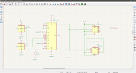
Today, while helping @mrcity I had to take some measures at the CPU clock and found that all existing references of the operating frequency for this computer are wrong. The computer's main oscillator vibrates at 18.432MHz, then it is divided by three using a 74LS112 to have a nominal 6.14MHz signal delivered on pin 1 of the CPU (mine oscillates between 6.10 and 6.17 but it's safe to suspect on the accuracy of my instrumentation). Pin 2 is not used.

20240717_190114.jpg
 
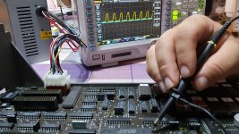
I have built a poor man's I/O probe to find the ports. While having some output at the device, it is not as stable as I thought it would be and therefore I have been unable to find the required addresses. I would like to ask if someone could take a revision on the schematics in order to find what I am doing wrong, please. I have the feeling that the issue might be a small one, but could be completely derailed. If I could put this device to work, we would be much nearer to having an emulator for this system than ever. Thank you in advance.
 

Attachments

  • Bits Passats - 8085 IO Probe.pdf
    74.9 KB · Views: 3
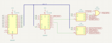
Today is proving to be a very productive day. Not only I have traced sections of the board near the display shift register but I also think some ports were found:

  • Service Port: 40h-43h
  • CRTC: 44h-47h
  • USART: 48h-4Bh
  • Keyboard Port: 4Ch-4Fh

Take this as a grain of salt, however. Reverse-engineering is not the easiest task, so I could perfectly be wrong.
 
Here are the schematics that should have come with my posts of the last two weeks.

S23-clock.png

Part of the timing circuit, where the path to the CPU is clarified. Since I made that screen capture, I have determined that pins 5,6,10 and 11 are tied together and that pin 9 is the video clock signal.

S23-iosel.png

The simple logic of I/O port decoding of the Datamaster. The latch is the one the 8085 uses to demultiplex the memory address bus.
 
I don't know if this week I would be able to study the datamaster. Nevertheless, after having obtained the i/o ports there is no preference for any section of the computer.

For this reason, I would like to ask you what part would you like to be mapped.

Thank you in advance
 
This week I continued to assist @mrcity with his unit. Tests are applied slowly, but I think we are on the good track. In order to help him I had to make some oscilloscope readings in the processor and noticed that on both computers' RST7.5 was always high. I suspect that, having the highest priority among the software-maskable interrupts it is tied up as a watchdog in the sense that ROM 02h may deactivate the interrupt as soon as the computer starts so in case such memory fails it is not deactivated and to prevent arbitrary code execution it is always jumps to 003Ch. This would happen before the initialization of the service port and therefore the probe would have all LEDs light. Note that I had no time to corroborate this on the software side so take it as a grain of salt.

Today I have a different question to ask you. I am aware not many people have this computer, even less are likely to study it so I understand that the thread has devolved into some kind of monologue. Investigating this computer is difficult, it can be overwhelming sometimes. When I ask for parts of the computer to be mapped is to help solving issues owners of this computer could have or by curiosity over the transition to the 5150 PC. As of lately, nobody has answered my questions... Have you already lost interest in this subject? Is something wrong? Can I do something to improve this thread?

Thank you in advance
 
I write to correct my previous statement about a watchdog. Yesterday I found RST7.5 is PIT timer 2. If the 8253 is faulty it can output a pulse without having even been configured, interrupting the CPU so often that it crashes.
 
I do regular checks of visibility of my article at my website so I browse with different search engines under the terms "IBM System/23 Datamaster" and strangely I found a fresh request of help (minus than a day). So I joined reddit only to help that user but seems oblivious to the fact I am trying to help... I want to help him but I am starting to run off of ideas.
 
I do regular checks of visibility of my article at my website so I browse with different search engines under the terms "IBM System/23 Datamaster" and strangely I found a fresh request of help (minus than a day). So I joined reddit only to help that user but seems oblivious to the fact I am trying to help... I want to help him but I am starting to run off of ideas.
Lol it's me still in need of help. I didn't know about this thread I can take pictures of my system if that could help you
 
Lol it's me still in need of help. I didn't know about this thread I can take pictures of my system if that could help you
Actually it is not casuality. I wrote this post so you could realize you were ignoring one of the few people that both could and wanted to help you.

Now, let's get to the point. Actually the same I told you at reddit.

Your faulty memory board, remove the capacitors with the "077" markings on top. They are on the +12V line. They are the culprits to your board failure.
How many piggybacked pairs do your memory boards have, 9 or 18?

Yes, a picture of the board could help, as well as pictures of the memory boards.
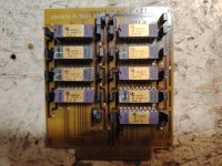
EDIT:
Placing only the working memory card at the "feature" slot should actually work if that module is in working condition.
 
Last edited:
Actually it is not casuality. I wrote this post so you could realize you were ignoring one of the few people that both could and wanted to help you.

Now, let's get to the point. Actually the same I told you at reddit.

Your faulty memory board, remove the capacitors with the "077" markings on top. They are on the +12V line. They are the culprits to your board failure.
How many piggybacked pairs do your memory boards have, 9 or 18?

Yes, a picture of the board could help, as well as pictures of the memory boards.
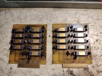
Sorry if it seem that I ignored you I'm 19 and English isn't my first language so I'm doing my best


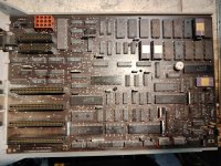
2024-09-0600.05.523841246845469068830.jpg2024-09-0600.02.414834961755813224625.jpg
2024-09-0523.58.573919722340484226617.jpg
 
Don't worry, no hard feelings. We managed to reach each other so the objective is fulfilled.

You have the same board version as me. That's nice for in case there's some nasty surprise later on.
I correct, in your case the capacitors to remove/replace are those with "951" markings on top. Have you tried the computer with only one of them?

By the way, you dethroned me as the youngest owner of a 5322.
 
Back
Top